Wide Area Shield for use in a Plasma Cutting Torch.

Inactive Publication Date: 2020-09-24
AMERICAN FLASHLIGHT TIP
View PDF0 Cites 1 Cited by
  • Summary
  • Abstract
  • Description
  • Claims
  • Application Information

AI Technical Summary

Benefits of technology

[0005]The present invention provides an extended life shield for use in a plasma cutting torch. The extension of the usable life of the plasma cutting torch shield is accomplished in part by increasing the amount of heat transfer from the water-cooled section of the shield by providing liquid cooling to the areas of the shield opposite or in proximity of the shielding surfaces, as well as increasing the amount of surface area, of the shield, exposed to liquid cooling. The life of the s

Problems solved by technology

The solidified spatter can build up on the plasma torch and cause several problems, such as thermal hot spots, blockage of flow chann

Method used


Image

  • Wide Area Shield for use in a Plasma Cutting Torch.
  • Wide Area Shield for use in a Plasma Cutting Torch.
  • Wide Area Shield for use in a Plasma Cutting Torch.

Examples


Embodiment Construction

[0015]Referring now to the drawings, wherein like reference numerals designate identical or corresponding parts throughout the several views, embodiments of the invention are shown. The present invention is a wide area shield for use in a plasma cutting torch.

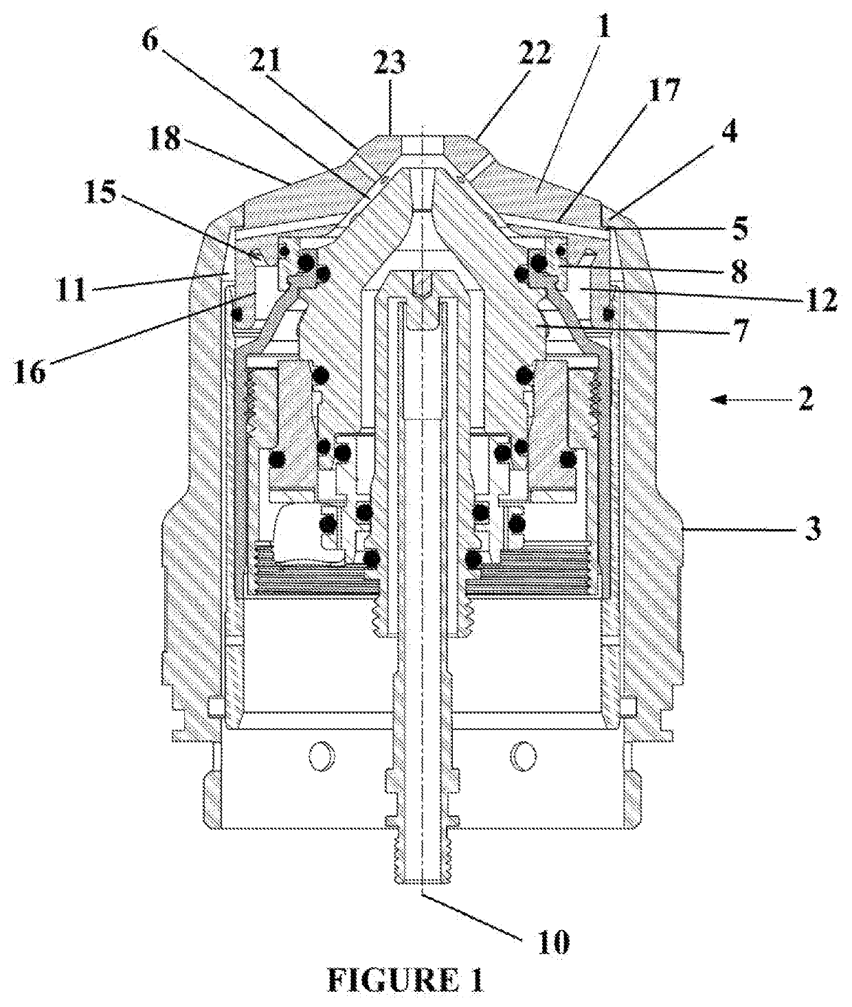
[0016]A cross sectional view of an embodiment of the present invention installed in a plasma cutting torch can be seen in FIG. 1. The wide area shield 1 can be seen in a plasma cutting torch assembly 2. The wide area shield 1 is located at the distal end of the cutting torch assembly 2 and is held in place concentrically, about central axis 10, to the plasma cutting torch assembly 2 by outer retaining cap 3 which is threaded to the plasma cutting torch body (not shown) and compresses the wide area shield 1 via a flange 4 on the inner diameter of the outer retaining cap 3 and lip 5 on the outer diameter of the wide area shield 1. The lip 5 of the wide area shield 1 represents ˜4.6% of the total diameter of the wide area shield 1...


PUM


Abstract

A wide area shield for use in a plasma cutting torch. The wide area shield has a projected surface that covers at least 75% of the distal end of the plasma cutting torch when viewed in a plane perpendicular to the central axis of the torch. The wide area shield is actively cooled by at least two separate cooling flows. One possible cooling flow is liquid and contacts at least 25% of the total surface area of the wide area shield. A second possible cooling flow is gaseous and contacts at least 6% of the total surface area of the wide area shield. The increased projected area is achieved by increasing the axial length of the shield and increasing the shielding surface of the wide area shield which also allows for a thicker cross-sectional area of the wide area shield as measured perpendicularly from the shielding surfaces.

Description

BACKGROUND OF THE INVENTIONA. Field of Invention[0001]The present invention is in the technical field of plasma cutting torches. More particularly, the present invention is in the technical field of consumables used to shield the nozzle of a plasma cutting torch during cutting operations.B. Description of Related Art[0002]Prior art plasma cutting torches have been well-known for many years and are used in cutting and piercing metal work pieces. Plasma cutting devices, such as plasma torches, use an anode and cathode to generate an electrical arc that ionizes a working gas, usually compressed air or oxygen. The plasma cutting torch begins the cutting process by circulating a working gas through the torch and out the nozzle, and onto a work piece, generally a piece of plate metal. The working gas is converted to a plasma state via a starting process that can require contact between the plasma torch and work piece to complete the necessary circuit or be a contact less means using an in...

Claims


Application Information

Patent Timeline
IPC IPC(8): H05H1/28
CPCH05H1/28H05H2001/3457H05H1/34H05H1/3457
Inventor DADIG, STEVEN E.MERRILL, MATTHEW JOEL
Owner AMERICAN FLASHLIGHT TIP
Why Eureka
Try Eureka