Check patentability & draft patents in minutes with Patsnap Eureka AI!

Flux enhanced high energy density welding

Inactive Publication Date: 2012-07-19
SIEMENS ENERGY INC
View PDF57 Cites 80 Cited by
  • Summary
  • Abstract
  • Description
  • Claims
  • Application Information

AI Technical Summary

Problems solved by technology

This contaminates the weld bead and the weld bead / joint may suffer in terms of strength and longevity.
However, atmospheric contamination of weld beads still occurs in the high energy density welding techniques, and thus there is room for improvement in the art.

Method used


Image

  • Flux enhanced high energy density welding
  • Flux enhanced high energy density welding
  • Flux enhanced high energy density welding

Examples


Embodiment Construction

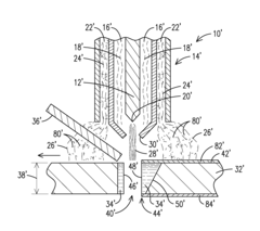
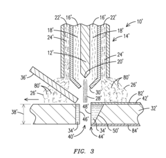
[0009]The present inventor has identified weaknesses in shielding methods used in high energy density welding techniques, and discloses a shielding method unique to these high energy welding techniques. This new high energy density welding shielding technique employs knowledge and materials already present in other welding techniques, and as such, implementation will be easy and inexpensive to incorporate. As a result of this innovation, quality and yields of welds made using high energy density welding techniques will increase at minimal cost.

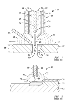
[0010]Conventional plasma arc welding 10 is illustrated in FIG. 1. In PAW, a tungsten or tungsten alloy electrode 12 is contained in a torch body 14. The torch body 14 further includes torch cavity 16 which contains the electrode 12 and delivers orifice gas 18 to the electrode tip 20, and a shielding gas path 22 for delivering discrete shielding gas 24 to the shielded region 26 of the weld. In PAW the electrode tip 20 does not protrude from th...


PUM

PropertyMeasurementUnit
Energyaaaaaaaaaa
Energy densityaaaaaaaaaa

Abstract

A method of shielding a weld. The method includes melting a substrate to form a weld pool using a high energy density welding technique of plasma arc welding, laser beam welding, or electron beam welding; and delivering a flux to the weld pool to produce a slag effective to shield against atmospheric contaminants.

Description

FIELD OF THE INVENTION[0001]The invention relates to the use of flux in high energy density welding techniques. Specifically, a technique for using flux in high energy density welding that may produce a shielding slag sufficient to shield a weld pool and a weld bead from atmospheric contaminants is disclosed.BACKGROUND OF THE INVENTION[0002]Substrates being welded and / or joined by a welding process need to be shielded from atmospheric contaminants. Otherwise, molten substrate material, formerly molten substrate material that is still heated, and heated substrate material in the region adjacent the location of the molten material (i.e. material in the heat affected zone) may react with the atmosphere (i.e. oxidize) and may absorb other contaminants present in the atmosphere. This contaminates the weld bead and the weld bead / joint may suffer in terms of strength and longevity.[0003]Welding techniques that utilize shielding may shield by any of several shielding methods. Shielded metal...

Claims


Application Information

Patent Timeline
IPC IPC(8): B23K9/16B23K9/18B23K25/00
CPCB23K9/324B23K26/1411B23K15/10B23K10/02B23K26/144
Inventor BRUCK, GERALD J.
Owner SIEMENS ENERGY INC
Features
  • R&D
  • Intellectual Property
  • Life Sciences
  • Materials
  • Tech Scout
  • Unparalleled Data Quality
  • Higher Quality Content
  • 60% Fewer Hallucinations
Learn More