UV enhancer for discharge lamp and manufacturing method thereof

Active Publication Date: 2012-07-19
IWASAKI ELECTRIC CO LTD
View PDF0 Cites 4 Cited by
  • Summary
  • Abstract
  • Description
  • Claims
  • Application Information

AI Technical Summary

Benefits of technology

[0027]In view of the above, it is a technical subject of the present invention to improve the starting performance by efficient irradiation of a UV-light by a necessary and sufficient amount into a discharge chamber of a high pressure discharge lamp and, at the same time, suppressing creeping discharge or atmosp

Problems solved by technology

However, since formation of the concave hole required many steps, it was troublesome and time consuming to result in a problem that not only the manufacturing cost was increased but also the yield was poor.
However, in a case of using the ring-shaped external electrode 65B as shown in FIG. 8, when the width of the ring is made large for increasing the UV-light output, since the light emitting chamber 64 of the glow discharge tube 63 is covered by the external electrode 65B, this

Method used


Image

  • UV enhancer for discharge lamp and manufacturing method thereof
  • UV enhancer for discharge lamp and manufacturing method thereof
  • UV enhancer for discharge lamp and manufacturing method thereof

Examples


embodiment 1

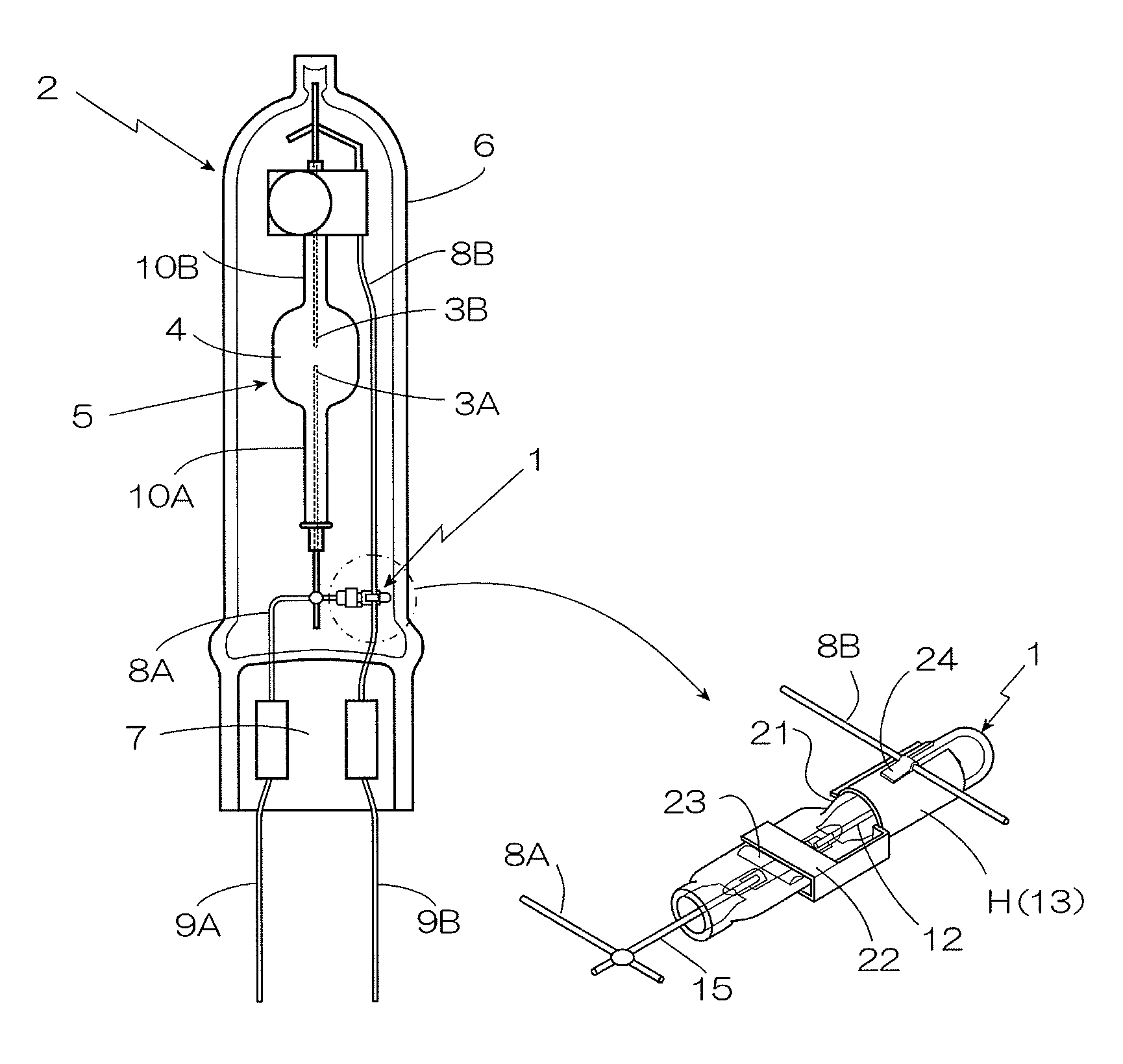
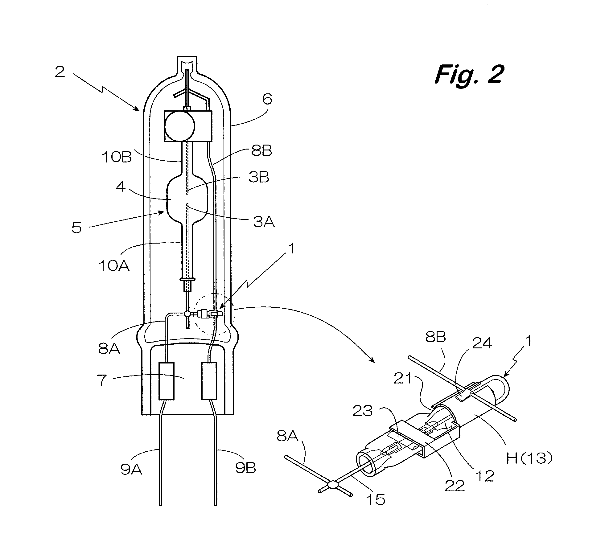
[0058]FIG. 2 shows a high pressure discharge lamp 2 provided with a UV enhancer 1 and having an arc tube 5 in which at least a light-emitting material and a starting gas are filled in a discharge chamber 4 where a pair of electrodes 3A and 3B are opposed to each other.

[0059]As the high pressure discharge lamp 2, a ceramic metal halide lamp containing the heat resistant arc tube 5 made of ceramics in an airtight tube 6 made of glass is used, and the UV enhancer 1 that constitutes a starting light source is disposed inside a seal tube 6.

[0060]One end of the seal tube 6 is hot pressed to form a pinch seal portion 7, a pair of power feed leads 9A and 9B connected to the electrode leads 8A and 8B protruding from both ends of the arc tube 5 are protruding from the pinch seal portion 7 to the outside of the seal tube 6, and connected to a lighting circuit (not illustrated).

[0061]In the ceramic arc tube 5, at least the light-emitting material and a starting gas are filled in the discharge c...

embodiment 2

[0095]FIG. 7 shows an embodiment of using a UV enhancer 1 mounted to a discharge lamp 101 of a light source device 100 of a projector, in which portions in common with those of FIG. 1 carry the same reference numerals for which detailed descriptions are to be omitted.

[0096]The light source device 100 has a high pressure discharge lamp 101 and a concave reflector 102 for reflecting a light emitted from the lamp 101.

[0097]In the high pressure discharge lamp 101, a pair of tungsten electrodes 106R and 106L are opposed to each other at a short inter-electrode distance of about 1 mm in a discharge chamber 105 of an arc tube 104 comprising quartz glass, mercury, halogen such as bromine, and a starting gas such as an argon gas are filled therein, and a pair of electrode sealed portions 109R and 109L are formed by airtightly sealing a portion from the discharge chamber 105 to both ends of the arc tube 104 and sealing each of the electrodes 106R and 106L, a metal foil 107 comprising a molybd...


PUM


Abstract

Starting performance is improved by efficient UV-light irradiation, suppressing creeping discharge or atmospheric discharge at the outside of a glow discharge tube, and preventing cracks in a pinch seal portion even when an external force is exerted in the direction of bending a lead. In a discharge tube for emitting a UV-light, a light emitting chamber is formed on one side of a pinch seal portion for sealing an electrode assembly, and a lead protrusion port is formed on the opposite side thereof while pinching the seal portion, the lead protrusion port is formed as a sleeve having a predetermined gap relative to the lead, an external electrode disposed to the outside of the light emitting chamber includes a hold formed by bending fabrication of a metal plate.

Description

TECHNICAL FIELD[0001]The present invention concerns a UV enhancer for discharge lamp provided to a discharge lamp including an arc tube in which at least a light-emitting material and a starting gas are filled and a pair of electrodes are opposed to each other in a discharge chamber, the UV enhancer having a discharge tube that irradiates a UV-light to the discharge chamber for enhancing the starting of the lamp, as well as a manufacturing method thereof.BACKGROUND ART[0002]In light source devices for liquid crystal projectors and DLP projectors which are required to be reduced in size and provide bright projection images, short arc type high pressure mercury vapor discharge lamps which are small in size and can provide light emission at high brightness have been used as the light source. Since the lamps of this type involve a problem that starting performance under cold conditions and restarting performance under hot restrike conditions are not generally preferred, a UV enhancer as...

Claims


Application Information

Patent Timeline
IPC IPC(8): H01J61/54H01J9/26
CPCH01J5/38H01J61/54H01J9/326
Inventor ISHIKAWA, YOUSUKEFUKUDA, NOBUOHARASAWA, HIROKAZUKOMATA, KOUJI
Owner IWASAKI ELECTRIC CO LTD
Why Eureka
Try Eureka