Plasma processing apparatus and gas supply device for plasma processing apparatus

Active Publication Date: 2012-07-26
TOKYO ELECTRON LTD
View PDF11 Cites 190 Cited by
  • Summary
  • Abstract
  • Description
  • Claims
  • Application Information

AI Technical Summary

Benefits of technology

[0040]In accordance with the plasma processing apparatus, it is possible to supply a film forming gas into a small-volume region formed between a mounting table and a head unit when the film forming gas is adsorbed on a target substrate. Thus, it is possible to reduce a supply amount of the film forming gas. Further, during the film forming process, a pressure is controlled not in the whole processing chamber of a large volume but in the small-volume region at a low flow rate. Thus, a time for controlling the pressure can be reduced. Therefore, it is possible to form a film efficiently. Furthermore, during the plasma process,

Problems solved by technology

However, if a silicon oxide film having a high insulation property is formed by the thermal CVD method, a silicon substrate needs to be exposed to high temperature.
Howeve

Method used


Image

  • Plasma processing apparatus and gas supply device for plasma processing apparatus
  • Plasma processing apparatus and gas supply device for plasma processing apparatus
  • Plasma processing apparatus and gas supply device for plasma processing apparatus

Examples


Example

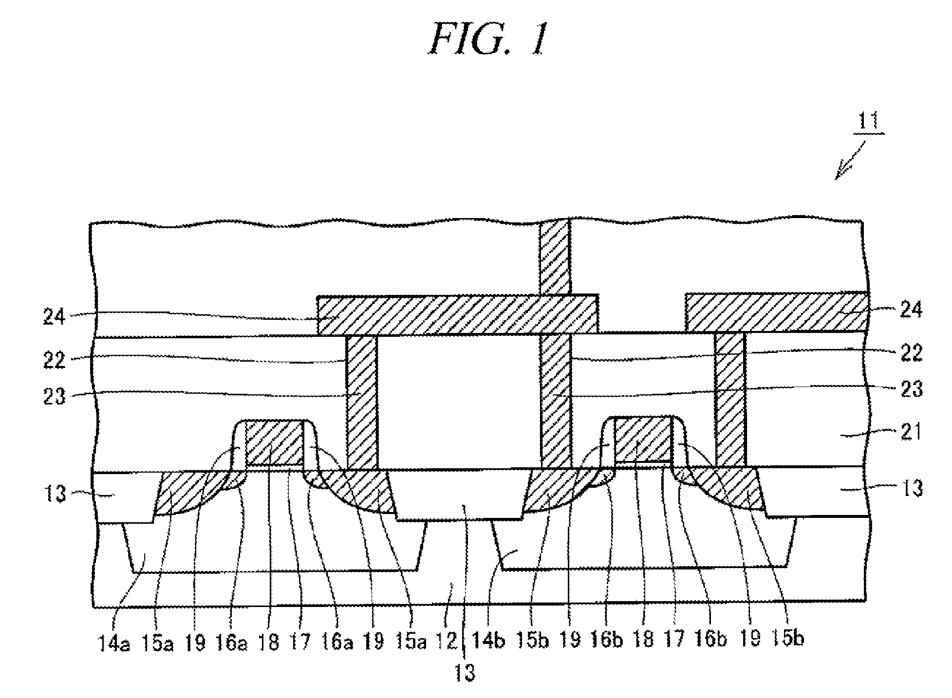
[0076]Hereinafter, illustrative embodiments will be described with reference to the accompanying drawings. A semiconductor device manufactured by a plasma processing apparatus in accordance with an illustrative embodiment will be explained. FIG. 1 is a schematic cross sectional view illustrating a part of a MOS-type semiconductor device manufactured by a plasma processing apparatus in accordance with the illustrative embodiment. In FIG. 1, a conductive layer of the MOS-type semiconductor device is hatched.

[0077]Referring to FIG. 1, a MOS-type semiconductor device 11 includes a silicon substrate 12 on which device isolation regions 13, p-wells 14a, n-wells 14b, high-concentration n-type impurity diffusion regions 15a, high-concentration p-type impurity diffusion regions 15b, n-type impurity diffusion regions 16a, p-type impurity diffusion regions 16b, and gate oxide films 17 are provided. One of the high-concentration n-type impurity diffusion regions 15a and the high-concentration p...


PUM

PropertyMeasurementUnit
Fractionaaaaaaaaaa
Temperatureaaaaaaaaaa
Dielectric polarization enthalpyaaaaaaaaaa

Abstract

A plasma processing apparatus 31 includes a processing chamber 32; a gas supply unit 33 for supplying a plasma processing gas into a processing chamber 32; a mounting table 34 configured to hold the target substrate W thereon; a plasma generating device 39 configured to generate plasma within the processing chamber 32; and a gas supply device 61. The gas supply device 61 includes a head unit 62 configured to move between a first position above the mounting table 34 and a second position different from the first position and to supply a gas, and the head unit 62 is configured to supply a film forming gas to a small-volume region formed between the mounting table 34 and the head unit 62 when the head unit 62 is positioned at the first position and to adsorb the film forming gas on the target substrate W.

Description

TECHNICAL FIELD[0001]The present disclosure relates to a plasma processing apparatus and a gas supply device for the plasma processing apparatus and, more particularly, to a plasma processing apparatus used for fabricating a semiconductor device and a gas supply device for the plasma processing apparatus.BACKGROUND ART[0002]Conventionally, when forming an insulating layer having a high pressure resistance property or an excellent leak property against a gate oxide film of a semiconductor device represented as a LSI (Large Scale Integrated Circuit) or a CCD (Charge Coupled Device) and a MOS (Metal Oxide Semiconductor) transistor, a thermal CVD (Chemical Vapor Deposition) method is generally used. However, if a silicon oxide film having a high insulation property is formed by the thermal CVD method, a silicon substrate needs to be exposed to high temperature. In this case, if a conductive layer is formed on the silicon substrate by using a material having a relatively low melting poin...

Claims


Application Information

Patent Timeline
IPC IPC(8): C23C16/50C23C16/511
CPCC23C16/45517C23C16/45536H01L21/02164H01L21/28194H01L21/02274H01L21/0228H01L21/0217H01L21/205H01L21/31
Inventor IWASAKI, MASAHIDENOZAWA, TOSHIHISA
Owner TOKYO ELECTRON LTD
Why Eureka
Try Eureka