Optical information reproducing method and optical information reproducing apparatus

a technology of optical information and reproducing apparatus, which is applied in the field of optical information reproducing method and optical information reproducing apparatus, can solve the problems of high-speed operation and large recording medium capacity, and achieve the effect of high speed and high precision

Inactive Publication Date: 2012-07-26
HITACHI CONSUMER ELECTRONICS CORP
View PDF10 Cites 10 Cited by
  • Summary
  • Abstract
  • Description
  • Claims
  • Application Information

AI Technical Summary

Benefits of technology

[0015]According to the present invention an incidence angle of the reference beam which is appropriate for reproduction can be detected with high precision and at high speed.

Problems solved by technology

However, the prior art method is large in consumption of the recording medium compared with a system of recording data by two values consisting of a bright part and a dark part, thus raising a problem in realizing a large capacity of recording medium.
Further, in order to control the angle of reading-out beam so as to make the diffracted beam have an extreme value, a series of operations must be repeated which include setting the angle of reading-out beam, detecting the intensity of diffracted beam, comparing the detected intensity of diffracted beam with the intensity of diffracted beam stored in a control circuit, and again setting the angle of the reading-out beam according to a comparison result, so that a problem arises in making a high-speed operation.

Method used


Image

  • Optical information reproducing method and optical information reproducing apparatus
  • Optical information reproducing method and optical information reproducing apparatus
  • Optical information reproducing method and optical information reproducing apparatus

Examples


embodiment 1

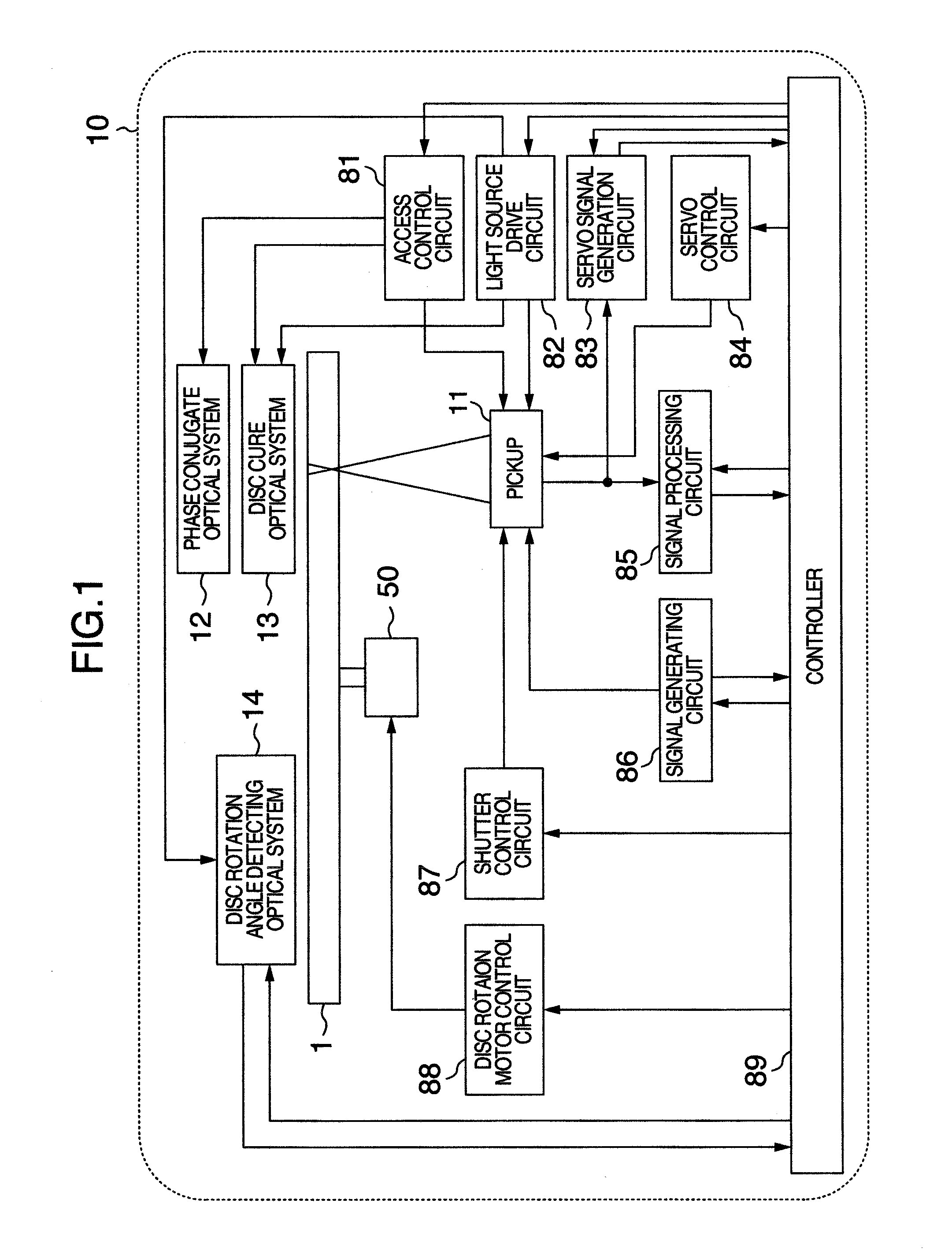
[0030]An embodiment of the present invention will now be described with reference to accompanying drawings. FIG. 1 shows in block diagram an optical information recording and reproducing apparatus which records and / or reproduces digital information utilizing holography.

[0031]An optical information recording and reproducing apparatus 10 includes a pickup 11, a phase conjugate optical system 12, a disc curing optical system 13, a disc rotating angle detecting optical system 14 and a rotating motor 50. An optical information recording medium 1 is configured to be rotatable by the rotating motor 50.

[0032]The pickup 11 plays a role of applying a reference beam and a signal beam to the optical information recording medium 1 and recording digital information on the recording medium 1 utilizing holography. At this time, the recorded digital information signal is sent to a spatial light modulator in the pickup 11 by a controller 89 through a signal generating circuit 86, and then the signal ...

embodiment 2

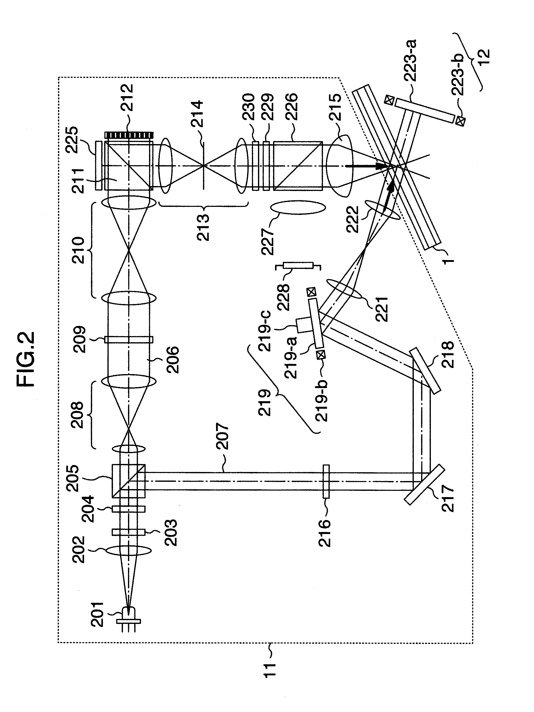
[0070]In the present embodiment, description will be made of a method for acquiring a suitable angle of reference beam collectively before reproduction over all pages in a book. The description of an optical system in the present embodiment will be omitted because the optical system is common to those as in FIGS. 2 and 3.

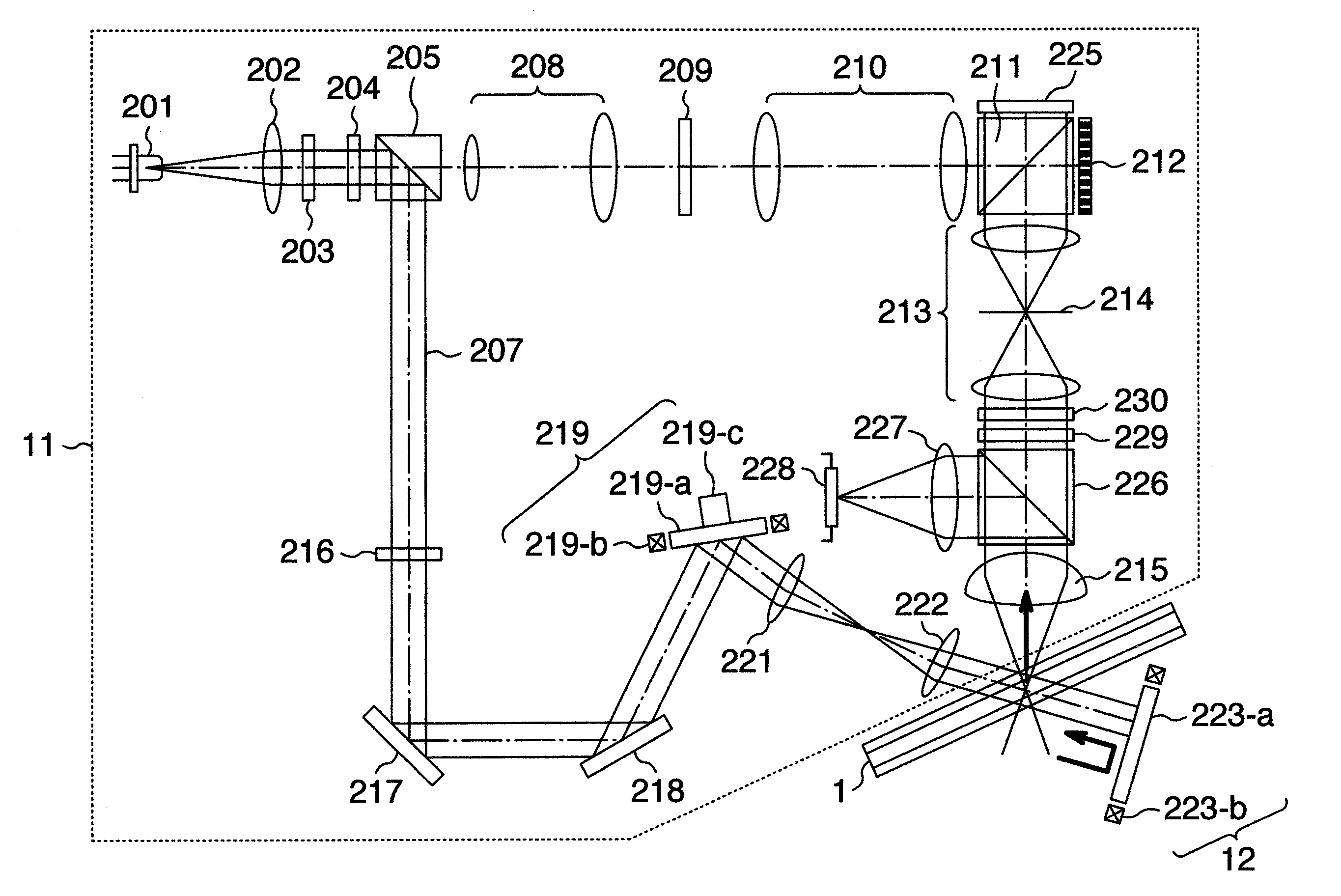
[0071]FIG. 10 shows an aspect of control of the reference beam angle according to the present embodiment. FIG. 11 shows an operation flow of angle scanning according to the present embodiment. Before reproduction of page data in the book, when the photodetector 228 detects the intensity of a diffracted beam with the angle of the reference beam being continuously scanned from the maximum angle to the minimum angle of an angle range within which the reference beam is multiplexed as to angle, waveforms with the maximum intensity of diffracted beam are acquired at suitable angle positions of diffracted beam of respective pages which have been angle-multiplexed, respecti...

embodiment 3

[0074]FIG. 12 shows the configuration of an optical system in the Embodiment 3. Compared with the configuration of FIG. 3 the mirror 218 is changed to an angle-variable mirror 232. The angle-variable mirror 232 includes a mirror 232-a and an actuator 232-b. The actuator 232-b makes the angle of mirror 232-a adjustable. In an example, as the angle-variable mirror 232 an MEMS mirror which is capable of high-speed driving though the angle scanning range is small compared with a galvanic mirror is used and can be operated in combination with the galvanic mirror. With such a configuration, the angle scanning range is made large, fast angle control is made possible and fast recording and reproduction can be realized.

[0075]The Embodiment 1 is configured such that the signal beam reflected by the PBS prism 226 is converged by the lens 227 and enters the photodetector 228 to detect the intensity of the diffracted beam. But, the present embodiment arranges an area-divided diffracting element ...


PUM


Abstract

An optical information reproducing method and apparatus using an angle-multiplex recording type holographic memory. An optical information recording medium is exposed to a reference beam, the intensity of a diffracted beam diffracted in the medium is detected by a photodetector, an error signal is generated based on a value obtained by differentiating the detected intensity of the diffracted beam based on an angle of the reference beam, so that a reference beam angle control element is subjected to a feedback control.

Description

INCORPORATION BY REFERENCE[0001]The present application claims priority from Japanese application JP2011-011511 filed on Jan. 24, 2011, the content of which is hereby incorporated by reference into this application.BACKGROUND OF THE INVENTION[0002]The present invention relates to an apparatus and method for reproducing information from a recording medium, using holography.[0003]Currently, based on Blu-ray Disc (BD) specifications using a blue-violet semiconductor laser, an optical disc having a recording density of as large as 50 GB may be commercialized even for consumer use. In the future, optical discs are desired to provide a large capacity comparable to the capacity of a HDD (hard disc drive) such as 100 GB to 1 TB.[0004]However, in order to realize such an optical disc of ultra-high density, a high-density storage technology of a new scheme is required which is different from the conventional high-density technology which resorts to a shorter wavelength and a higher objective ...

Claims


Application Information

Patent Timeline
Patent Type & Authority Applications(United States)
IPC IPC(8): G03H1/02
CPCG11B7/08564G11B7/083
Inventor ISHII, TOSHIKISHIMADA, KENICHI
Owner HITACHI CONSUMER ELECTRONICS CORP
Why Eureka
Try Eureka