
DISORDERED MOLECULAR SIEVE SUPPORTS FOR THE SELECTIVE CATALYTIC REDUCTION OF NOx

a technology of molecular sieve supports and catalytic reduction, which is applied in the direction of physical/chemical process catalysts, arsenic compounds, separation processes, etc., can solve the problems of secondary emissions of non-selective reactions with oxygen or unproductive consumption of ammonia, and achieve good thermal and hydrothermal stability and improve the effect of nh3—scr activity

Active Publication Date: 2012-07-26
JOHNSON MATTHEY PLC
View PDF0 Cites 35 Cited by
  • Summary
  • Abstract
  • Description
  • Claims
  • Application Information

AI Technical Summary

Benefits of technology

This patent describes a new type of catalyst for reducing NOx in gases. The catalyst is made by supporting transition metals on a special type of molecular sieve that has a disorder or is made up of multiple frameworks. This new catalyst has improved activity and stability compared to traditional catalysts. It can also tolerate repeated high temperature aging. The support itself may also have some catalytic activity, making it a more versatile catalyst. The method for reducing NOx involves exposing the gas with the reactant to the new catalyst.

Problems solved by technology

Competing, non-selective reactions with oxygen can produce secondary emissions or may unproductively consume ammonia.

Method used


Image

  • DISORDERED MOLECULAR SIEVE SUPPORTS FOR THE SELECTIVE CATALYTIC REDUCTION OF NOx
  • DISORDERED MOLECULAR SIEVE SUPPORTS FOR THE SELECTIVE CATALYTIC REDUCTION OF NOx
  • DISORDERED MOLECULAR SIEVE SUPPORTS FOR THE SELECTIVE CATALYTIC REDUCTION OF NOx

Examples


example 1

Preparation of Copper-Loaded AEI / CHA Intergrowth Molecular Sieves

[0073]A sample of a molecular sieve material was obtained and tested to determine its structure and composition. For the sample, an X-ray Diffraction (XRD) pattern was collected on a PANalytical X'Pert PRO MPD (Multi-Purpose Diffractometer), using a copperradiation. The diffraction pattern was collected using programmable divergence and receiving slit maintaining a constant sample illuminated area of 10 mm and the x-rays were measured using a Real Time Multiple Strip (RTMS) detector. DIFFaX analysis was used to determine the AEI / CHA intergrowth ratio. DIFFaX is a program used to simulated powder diffraction data. The program is available from the International Zeolite Association or from the authors Michael M. J. Treacy and Michael W. Dean. The version used to generate the simulations was DIFFaX 1.813. The input file used to generate the simulation was the same as detailed in the document WO 02 / 070407. The simulati...

example 2

NOx Performance of Copper-Loaded AEI / CHA Intergrowth Molecular Sieves

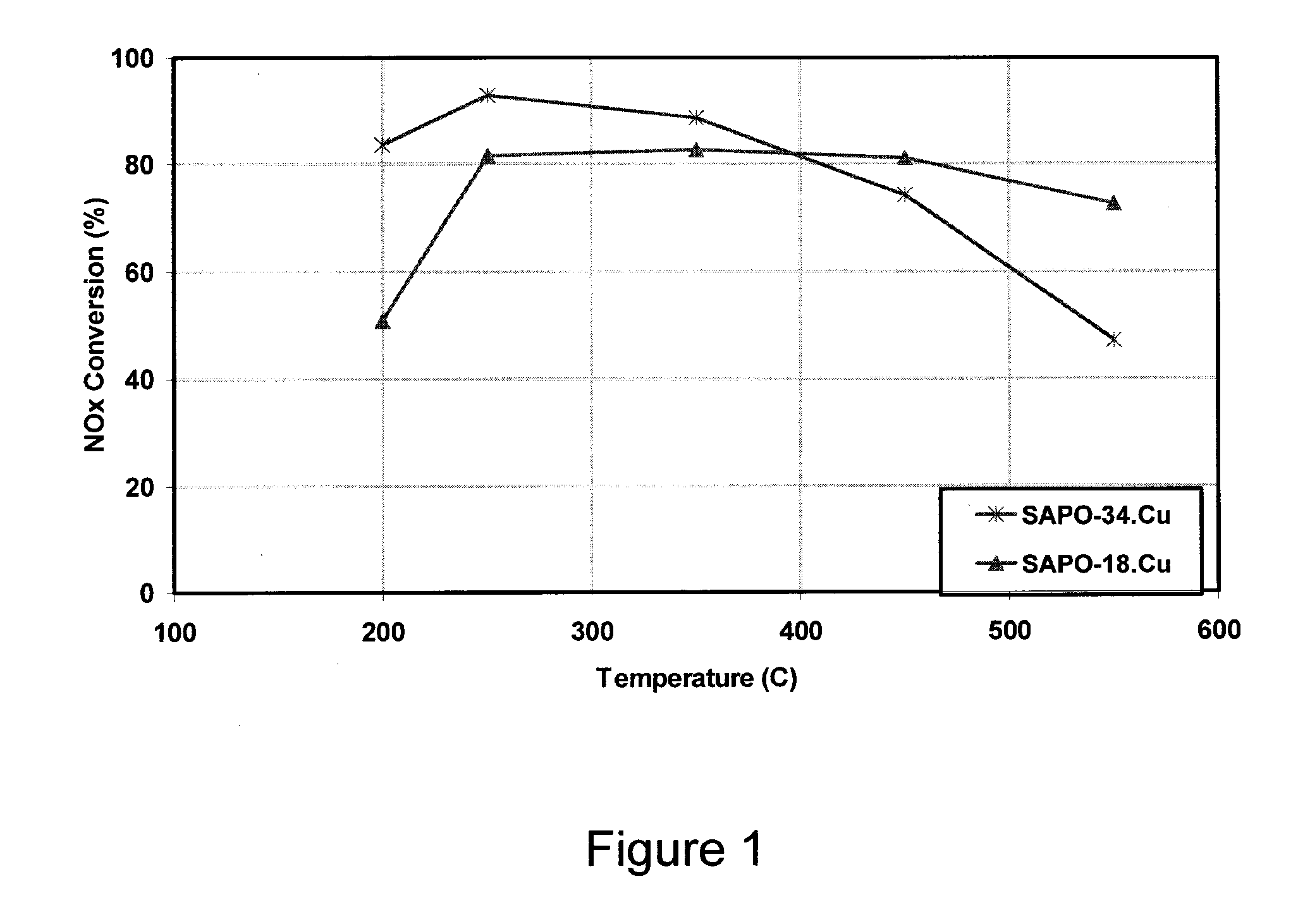
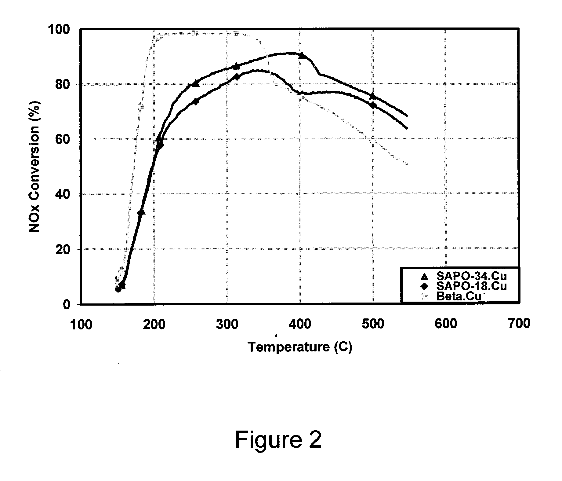
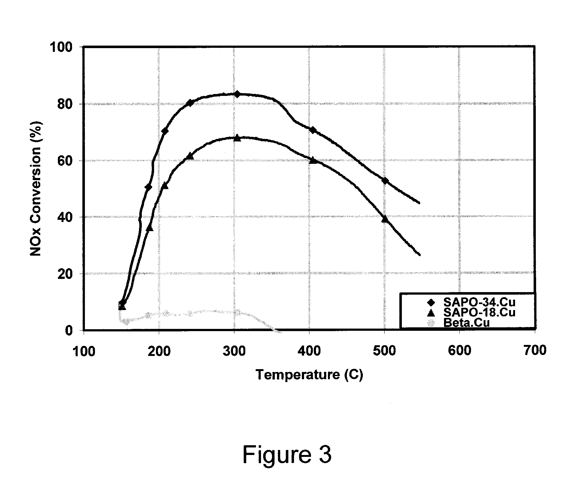
[0077]The copper-loaded 10:90 AEI / CHA intergrowth sample was hydrothermally aged for 72 hours at 700° C. The aged material was then applied as a washcoat to a monolith honeycomb core and tested using a Synthetic Catalyst Activity Test (SCAT) rig. The testing was performed under simulated diesel exhaust gas conditions, namely exposing the catalyst to a gas at a space velocity of 50,000 / hour, wherein the gas composition was about 350 ppm NH3 and NO, about 14 weight % O2, about 4.5 weight % H2O, and about 5 weight % CO2 in N2. The test temperature ranged from 200 to 450° C.

[0078]The sample was tested to determine its capacity for NO conversion (e.g. into N2 and O2) as a function of temperature. The results are shown in FIG. 9.

[0079]For comparison, a sample having only a CHA framework was also tested. The comparative sample was loaded with a similar amount of copper, underwent similar hydrothermal aging, and was tested...


PUM

PropertyMeasurementUnit
temperatureaaaaaaaaaa
aaaaaaaaaa

Abstract

A catalyst for selective catalytic reduction of NOx having one or more transition metals selected from Cr, Mn, Fe, Co, Ce, Ni, Cu, Zn, Ga, Mo, Ru, Rh, Pd, Ag, In, Sn, Re, Ir, Pt, and mixtures thereof supported on a support, wherein the support has a molecular sieve having at least one intergrowth phase having at least two different small-pore, three-dimensional framework structures.

Description

CROSS-REFERENCE TO RELATED APPLICATIONS[0001]This application is a continuation of PCT International Application No. PCT / US2011 / 028123, filed Mar. 11, 2011, and claims priority of U.S. Provisional Application No. 61 / 312,832, filed Mar. 11, 2010, the disclosures of both of which are incorporated herein by reference in their entireties for all purposes.FIELD OF THE INVENTION[0002]The present invention relates to supports used for catalysts in selective catalytic reduction.BACKGROUND OF THE INVENTION[0003]Selective catalytic reduction (SCR) of NOx by nitrogenous compounds, such as ammonia or urea, has developed for numerous applications including for treating industrial stationary applications, thermal power plants, gas turbines, coal-fired power plants, plant and refinery heaters and boilers in the chemical processing industry, furnaces, coke ovens, municipal waste plants and incinerators, and a number of vehicular (mobile) applications, e.g., for treating diesel exhaust gas.[0004]Sev...

Claims


Application Information

Patent Timeline
Patent Type & Authority Applications(United States)
IPC IPC(8): B01D53/56B01D53/94
CPCB01D53/9418B01J2229/18B01D2255/1021B01D2255/2073B01D2255/20738B01D2255/20746B01D2255/20761B01D2255/50B01D2257/404B01D2258/012B01J29/72B01J29/723B01J29/80B01J35/04B01J37/0246B01J2229/62B01J29/783B01J29/005B01J29/78B01J29/85B01D2251/2062B01J35/56B01J35/30B01J2235/15B01D53/56B01D53/8628B01J23/10B01J29/763B01J29/072B01J29/46B01J29/56B01J29/7615B01J29/7676B01J29/83B01J37/0009B01J37/16B01J23/72B01D2251/208B01D2255/9202B01D2258/018B01D2258/0291B01J2229/42B01D2253/1122Y02A50/20B01J29/061B01J2029/062
Inventor ANDERSEN, PAUL J.CASCI, JOHN LEONELLOCHEN, HAI-YINGFEDEYKO, JOSEPH M.
Owner JOHNSON MATTHEY PLC
Learn More