Distributed external and internal wireless sensor systems for characterization of surface and subsurface biomedical structure and condition

a biomedical structure and condition technology, applied in the field of sensing systems, can solve the problems of local remodeling and resorption that affect the geometry and mechanical properties of the bone, increase the risk of wear or fracture, and increase the risk of structural variations

Inactive Publication Date: 2012-07-26
RGT UNIV OF CALIFORNIA
View PDF9 Cites 223 Cited by
  • Summary
  • Abstract
  • Description
  • Claims
  • Application Information

AI Technical Summary

Benefits of technology

[0017]An aspect of this invention is the in situ sensing and monitoring of skin or wound or ulcer status using a wireless, biocompatible RF powered sensor system referred to as smart patch, smart band-aid or smart cast. This invention enables the realization of smart preventive measure...

Problems solved by technology

These mechanical alterations in the femur cause local remodeling and resorption that affect the geometry and mechanical properties of the bone.
Using such implants in the long run will cause considerable pressure/friction/strain on the structure/joint and hence increased risk of wear or fracture or problematic structural variations.
Findings now suggest that a significant number exhibit wear that causes serious problems, including particulate matter developed by wear which produces toxic reactions, which can have serious effects on the health of the patients.
Implant failures include instability and dislocation, mechanical loosening, wear and corrosion and infection.
Patients, who are increasingly younger, are less compliant than desirable due to the fact that they can lose pain sensation in their affected joint.
Additionally, the improvements in the joint surgeries have resulted in patients feeling better about the...

Method used


Image

  • Distributed external and internal wireless sensor systems for characterization of surface and subsurface biomedical structure and condition
  • Distributed external and internal wireless sensor systems for characterization of surface and subsurface biomedical structure and condition
  • Distributed external and internal wireless sensor systems for characterization of surface and subsurface biomedical structure and condition

Examples


embodiment 1

[0177]2. The system of wherein the electromagnetic energy comprises RF energy; wherein the sensor elements comprise a plurality of sensor or emitter electrodes; and wherein the antenna comprises an RF coil configured to inductively power at least one of the electrodes.

[0178]3. The system of embodiment 1: wherein the electromagnetic energy comprises the sole source of power to the array.

[0179]4. The system of embodiment 1, wherein the electromagnetic waveform comprises a data signal; and wherein the data signal comprises instructions readable by said processor for controlling the one or more elements.

[0180]5. The system of embodiment 1: wherein the electromagnetic energy comprises an optical waveform; wherein the sensor elements comprise a plurality of optical sensors or emitters; and wherein the antenna comprises an optical receiver configured to inductively power at least one of the optical sensors or emitters.

[0181]6. The system of embodiment 1: wherein the electromagnetic energy...

embodiment 4

[0183]8. The system of embodiment 4, wherein the array further comprises a signal demodulator to demodulate the electromagnetic signal for processing by the processor.

embodiment 8

[0184]9. The system of embodiment 8, wherein the array further comprises a signal modulator for transmitting a return data signal relating to said physiological characteristic from the array to the interrogator.

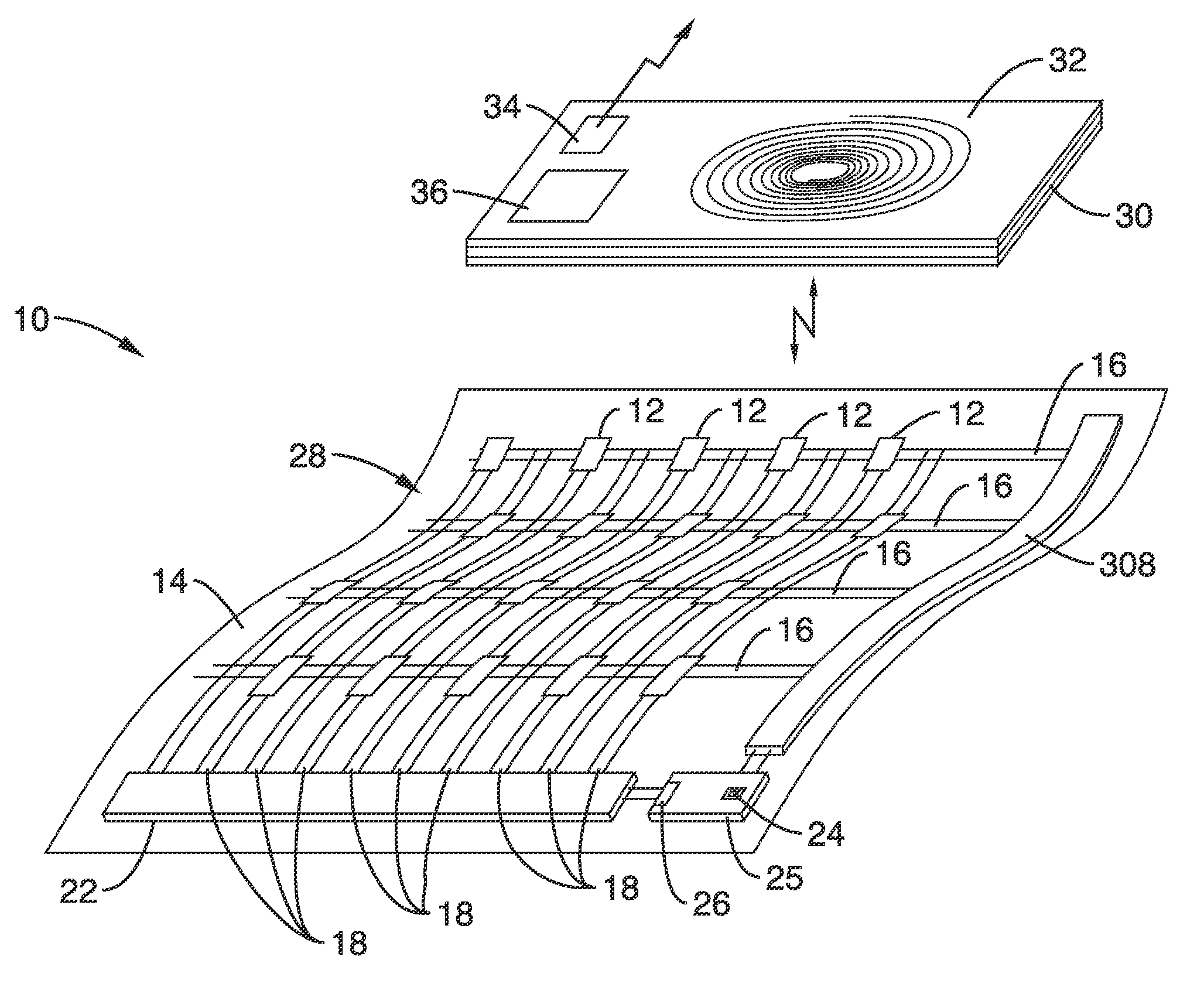
[0185]10. The system of embodiment 1, wherein the sensor elements are disposed at intersections of row and column transmission lines; and wherein said transmission lines are coupled to said processor for individual control of the sensor elements.

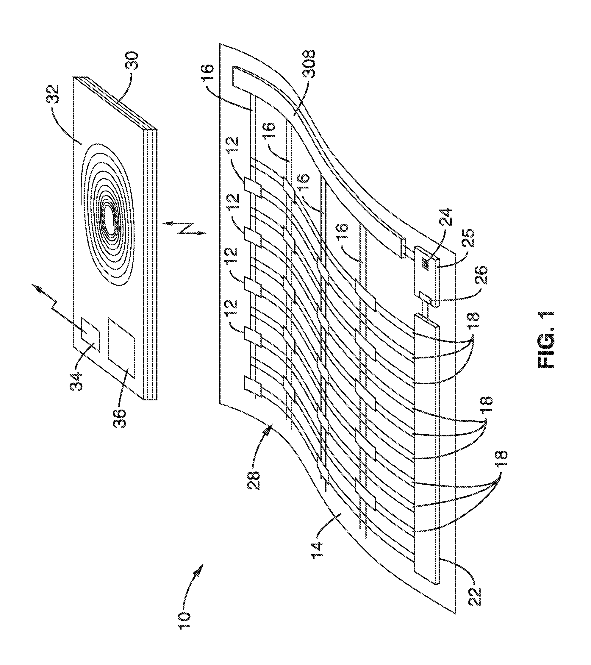
[0186]11. The system of embodiment 1, wherein the array is configured to comprise at least one emitter element configured to emit a signal into the internal tissue region and at least on sensor element configured to receive a reflected signal from said tissue region; wherein the reflected signal comprises at least one physiological characteristic of said tissue region.

[0187]12. The system of embodiment 1, wherein the sensor array comprises a first sensor array, the system further comprising: a second array of sensor elements; the seco...


PUM


Abstract

Systems and methods are disclosed that use wireless coupling of energy for operation of both external and internal devices, including external sensor arrays and implantable devices. The signals conveyed may be electronic, optical, acoustic, biomechanical, and others to provide in situ sensing and monitoring of internal anatomies and implants using a wireless, biocompatible electromagnetic powered sensor systems.

Description

CROSS-REFERENCE TO RELATED APPLICATIONS[0001]This application a 35 U.S.C. §111(a) continuation of PCT international application number PCT / US2010 / 045784 filed on Aug. 17, 2010, which is a nonprovisional of U.S. provisional patent application Ser. No. 61 / 234,494 filed on Aug. 17, 2009, and a nonprovisional of U.S. provisional patent application Ser. No. 61 / 234,506 filed on Aug. 17, 2009, and a nonprovisional of U.S. provisional patent application Ser. No. 61 / 234,524 filed on Aug. 17, 2009, each of which is incorporated herein by reference in its entirety. Priority is claimed to each of the foregoing applications.[0002]The above-referenced PCT international application was published as PCT International Publication No. WO 2011 / 022418 published on Feb. 24, 2011 and republished on May 5, 2011, each of which is incorporated herein by reference in its entirety.STATEMENT REGARDING FEDERALLY SPONSORED RESEARCH OR DEVELOPMENT[0003]Not ApplicableINCORPORATION-BY-REFERENCE OF MATERIAL SUBMITTE...

Claims


Application Information

Patent Timeline
IPC IPC(8): A61B5/00A61B5/05A61B5/03A61B6/00A61B5/01
CPCA61B5/0031A61F2002/043A61B5/01A61B5/053A61B5/08A61B5/445A61B5/4528A61B5/6804A61B5/6833A61B7/005A61B7/006A61B2560/0214A61B2562/0261A61B2562/0271A61B2562/164A61F2/82A61B5/0059A61B5/015A61B5/02158A61B5/0537A61B5/291
Inventor KAISER, WILLIAM J.SARRAFZADEH, MAJIDABERLE, DENISEBATALIN, MAXIMMEHRNIA, ALIREZANAHAPETIAN, ANISAYRE, JAMES
Owner RGT UNIV OF CALIFORNIA
Why Eureka
Try Eureka