System and Method for Localization of Large Numbers of Fluorescent Markers in Biological Samples

a fluorescent marker and biological sample technology, applied in material analysis using wave/particle radiation, instruments, nuclear engineering, etc., can solve the problems of limiting the application of fms, affecting the image quality, and many minutes of imaging,

Active Publication Date: 2012-08-02
FEI CO
View PDF8 Cites 110 Cited by
  • Summary
  • Abstract
  • Description
  • Claims
  • Application Information

AI Technical Summary

Benefits of technology

[0008]One embodiment comprises a detector optics configuration which presents a very large collection solid angle for both secondary electrons and emitted light, without interference between the two types of detectors which would tend to reduce the respective collection solid angles for both SEs and light.

Problems solved by technology

Many of the prior art methods for localization of FMs within biological samples work only for relatively small numbers of FMs, from which a small subset are activated at any one time—thus imaging times can be many minutes and still suffer from some of the limitations of light optical imaging.
Prior art methods employing charged particle beams to selectively damage FMs within samples have utilized image processing methods capable of dealing only with relatively small numbers of FMs—for these methods, the statistical signal-to-noise ratio limits their application to FMs which do not inherently appear in large densities.

Method used


Image

  • System and Method for Localization of Large Numbers of Fluorescent Markers in Biological Samples
  • System and Method for Localization of Large Numbers of Fluorescent Markers in Biological Samples
  • System and Method for Localization of Large Numbers of Fluorescent Markers in Biological Samples

Examples


first embodiment

Detector Optics Above the Sample

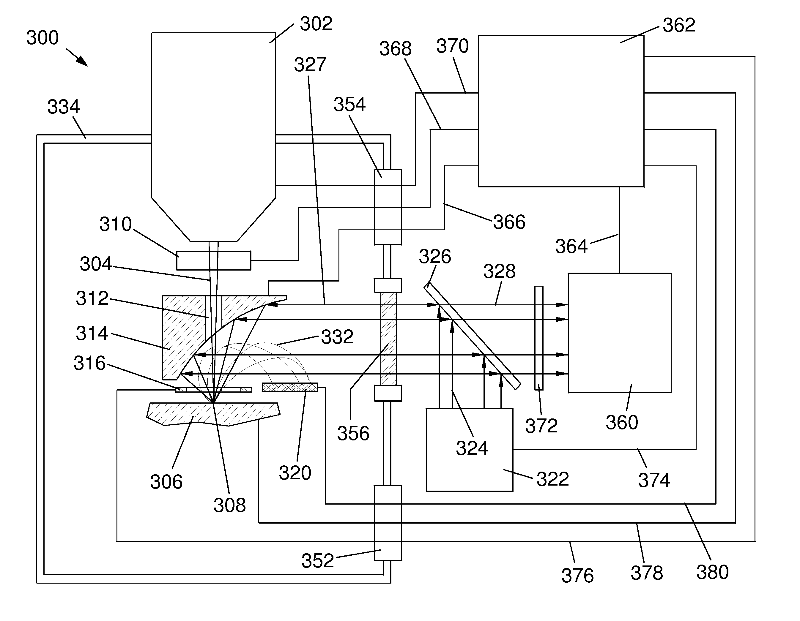
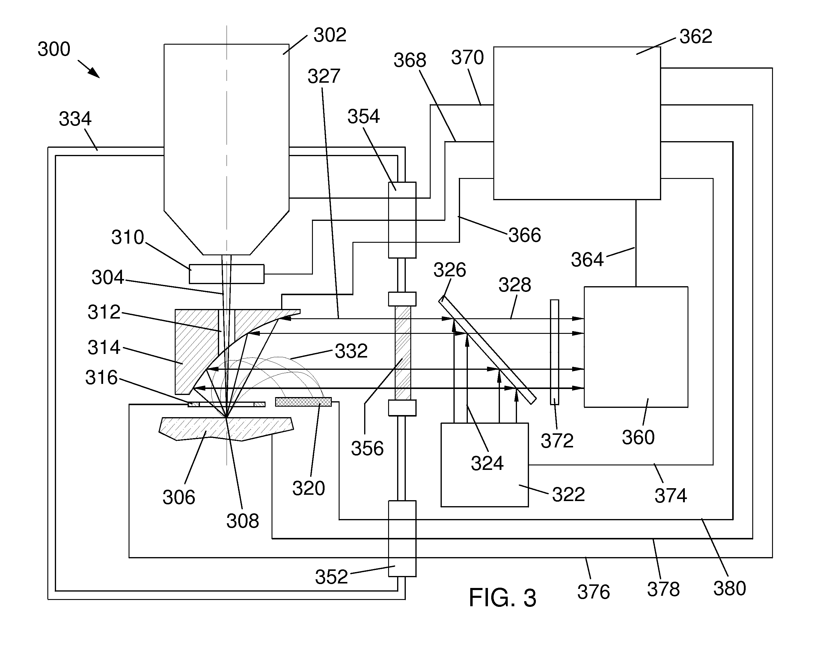
[0043]FIG. 3 is a schematic diagram of a first embodiment 300 of the present invention comprising detector optics above the sample 306. Sample 306 may include a biological sample including fluorescent markers that are expressed by genes linked to genes of interest or including inorganic markers that selectively attach to particular intracellular components. Sample 306 may also include a biological sample including dyes or other inorganic markers, such as quantum dots, that are functionalized to enable selective attachment to particular intracellular components. Sample 306 sits on a sample stage at a sample position that defines a sample plane.

[0044]A charged particle column 302, such as an electron beam column or a focused ion beam column, generates a beam 304 of charged particles that is focused by column 302 onto the surface of a sample 306 at a location 308. Electrons in the beam typically have energies of between 1,000 eV and 25,000 eV. Ions typic...

second embodiment

Detector Optics Below the Sample

[0052]FIG. 5 is a schematic diagram of a second embodiment 500 of the present invention comprising detector optics below a sample 506. A charged particle column 502, such as an electron beam column or a focused ion beam column, generates a beam 504 of charged particles which is focused by column 502 onto the surface of the sample 506 at a location 508. Beam 504 typically includes electrons having energies between about 50 keV and 300 keV. An X-Y beam deflector 510, which may comprise magnetic coils, electrostatic multipoles, or a combination of both magnetic coils and electrostatic multipoles, is configured to move the beam 504 around on the surface of the sample 506, typically in an X-Y raster pattern for imaging. In this second embodiment 500 of the invention, the sample 506 is assumed to be thin enough to permit penetration of the beam 504 through the sample 506, thus all imaging signals (both light and charged particles) are collected below the sa...

third embodiment

Detector Optics both Above and Below the Sample

[0056]FIG. 6 is a schematic diagram of a third embodiment 600 of the present invention comprising detector optics both above and below the sample 606. A charged particle column 602, such as an electron beam column or a focused ion beam column, generates a beam 604 of charged particles which is focused by column 602 onto the surface of a sample 606 at a location 608. An X-Y beam deflector 610, which may comprise magnetic coils, electrostatic multipoles, or a combination of both magnetic coils and electrostatic multipoles, is configured to move the beam 604 around on the surface of the sample 606, typically in an X-Y raster pattern for imaging. In this third embodiment 600 of the invention, the sample 606 is assumed to be thin enough to permit penetration of the beam 604 through the sample 606. To achieve larger collection efficiencies for light, two paraboloidal minors 614 and 680 are positioned above and below the sample 606, respective...


PUM

PropertyMeasurementUnit
diameteraaaaaaaaaa
diameteraaaaaaaaaa
FWHMaaaaaaaaaa

Abstract

A method and system for the imaging and localization of fluorescent markers such as fluorescent proteins or quantum dots within biological samples is disclosed. The use of recombinant genetics technology to insert “reporter” genes into many species is well established. In particular, green fluorescent proteins (GFPs) and their genetically-modified variants ranging from blue to yellow, are easily spliced into many genomes at the sites of genes of interest (GoIs), where the GFPs are expressed with no apparent effect on the functioning of the proteins of interest (PoIs) coded for by the GoIs. One goal of biologists is more precise localization of PoIs within cells. The invention is a method and system for enabling more rapid and precise PoI localization using charged particle beam-induced damage to GFPs. Multiple embodiments of systems for implementing the method are presented, along with an image processing method relatively immune to high statistical noise levels.

Description

TECHNICAL FIELD OF THE INVENTION[0001]The present invention relates generally to focused charged particle beam systems and, in particular, to systems used to excite and localize fluorescent markers in a sample.BACKGROUND OF THE INVENTION[0002]Biological research today is increasingly focusing on determining the positions within the cell of various cellular components to ever higher spatial resolutions. This involves many different techniques for enhancing resolution and contrast in images, both for electron microscopes (TEMs, STEMs, SEMs, etc.), as well as all types of light microscopes, including the latest super-resolution techniques. One powerful technique that has gained wide acceptance for research into cellular structure, transport, metabolism, and motility is the application of recombinant genetic techniques to link “reporter” genes to “genes of interest” (GoIs). Thus, when a particular GoI is expressed during normal genetic transcription / translation processes, the reporter g...

Claims


Application Information

Patent Timeline
Patent Type & Authority Applications(United States)
IPC IPC(8): G01N23/225G01N23/00
CPCG01N21/6428G01N21/6458H01J37/228G01N23/225H01J2237/206H01J2237/24455H01J2237/2803H01J37/28G01N21/6486H01J37/285H01J2237/2443H01J2237/2448H01J2237/2857
Inventor PARKER, N. WILLIAMUTLAUT, MARK W.
Owner FEI CO
Why Eureka
Try Eureka