
Wireless network element and method for antenna array control

Active Publication Date: 2012-08-02
ANALOG DEVICES INT UNLTD
View PDF12 Cites 54 Cited by
  • Summary
  • Abstract
  • Description
  • Claims
  • Application Information

AI Technical Summary

Benefits of technology

[0020]Accordingly, the invention seeks to mitigate, alleviate or eliminate one or more of the above mentioned disadvantages singly or in any combination.

Problems solved by technology

Electromechanical beam manipulation is limited to minor changes in tilt angle (typically up to 10°).
However, with such vertical / horizontal azimuth plane beam steering it is known that angle of arrival information of incoming signals is not capable of being discerned.
This is known to be a slow and expensive process.
Furthermore, such slow changes can not be dynamically adapted to user population changes within the network.
Thus, when thermal noise is added to the incident signals, the signals from multiple sources do not experience the same processing gain as a coherent desired signal.
Likewise UEs requiring higher data rate services will require all UEs to compensate for higher Eb / No required of the Node B. This increase in transmit power by the UE can be detrimental to network performance.
This effect poses a number of problems to WCDMA networks.
For example, the noise floor of the communication cell is increased, which in turn causes a propagation effect on the network and reduces data transmission rates.
Furthermore, UE devices consequently consume more power, as uplink transmissions are required to operate at higher power levels.
In addition, limitations exist on maximum throughput per cell as a result of dynamic range limitations imposed on UE transmissions.
Individual receive beam-forming for a specific user is not feasible, since there is likely to be multiple received signals of the same power from different UEs simultaneously at the antenna array.
In U.S. Pat. No. 5,889,494 the scanning apparatus describes a selection device of fixed beams being processed and does not disclose any technique for dynamically changing a beam.
However, U.S. Pat. No. 7,072,692 fails to describe any realizable implementation of how to generate such narrow beams.
Beamform generation of this accuracy would require a large array of antenna elements, which is not practical from a cost / power or size perspective with current wireless cellular systems.

Method used


Image

  • Wireless network element and method for antenna array control
  • Wireless network element and method for antenna array control
  • Wireless network element and method for antenna array control

Examples


Embodiment Construction

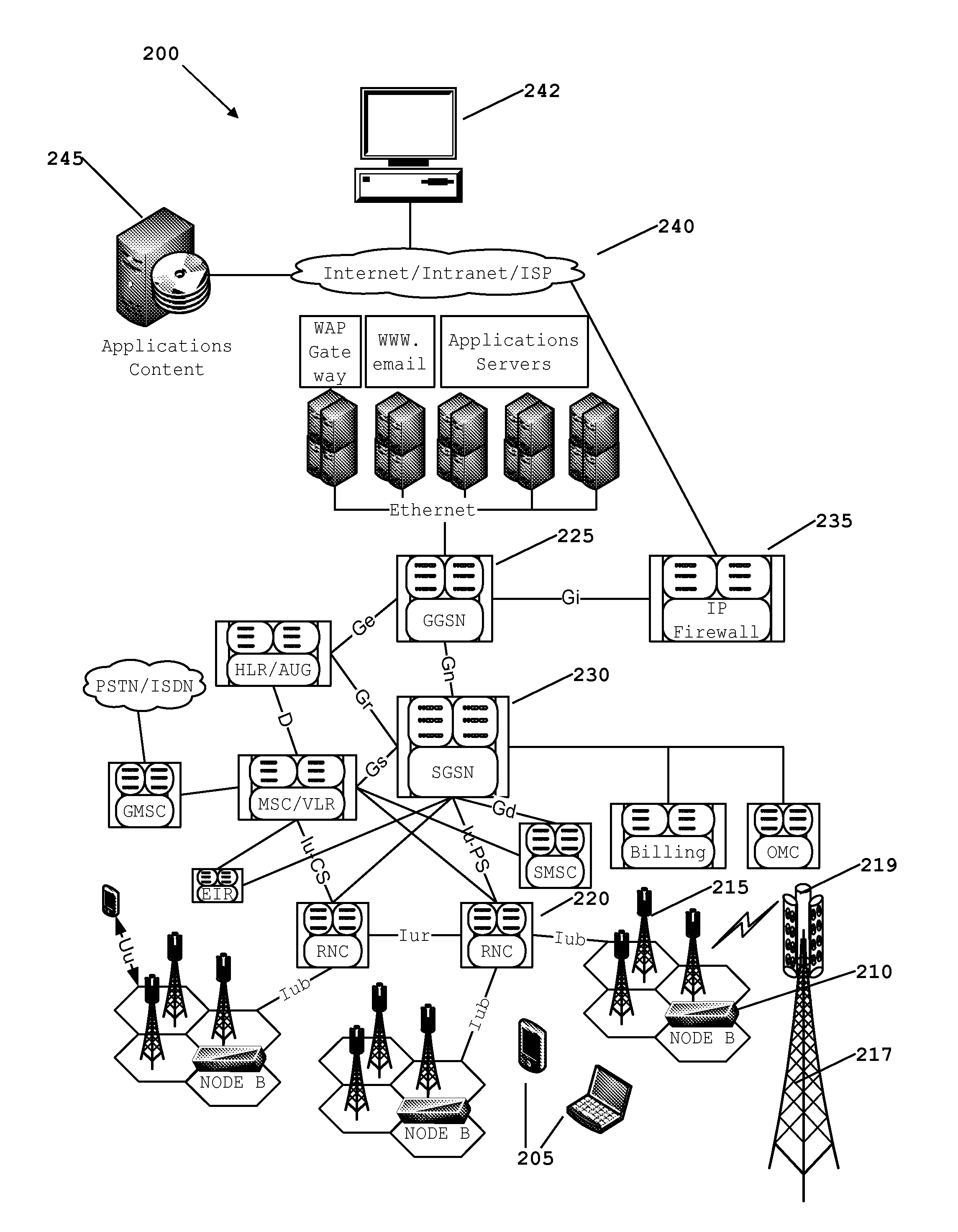
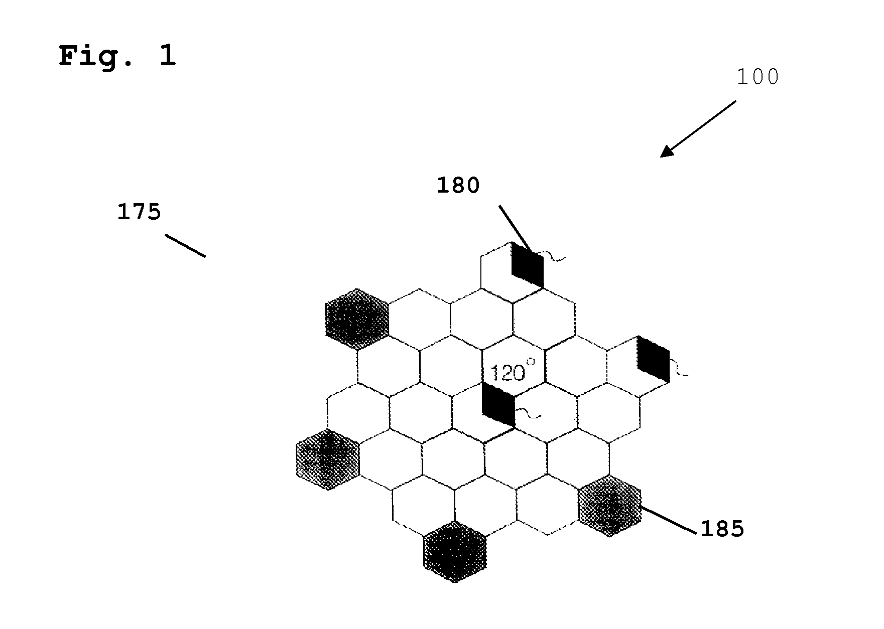
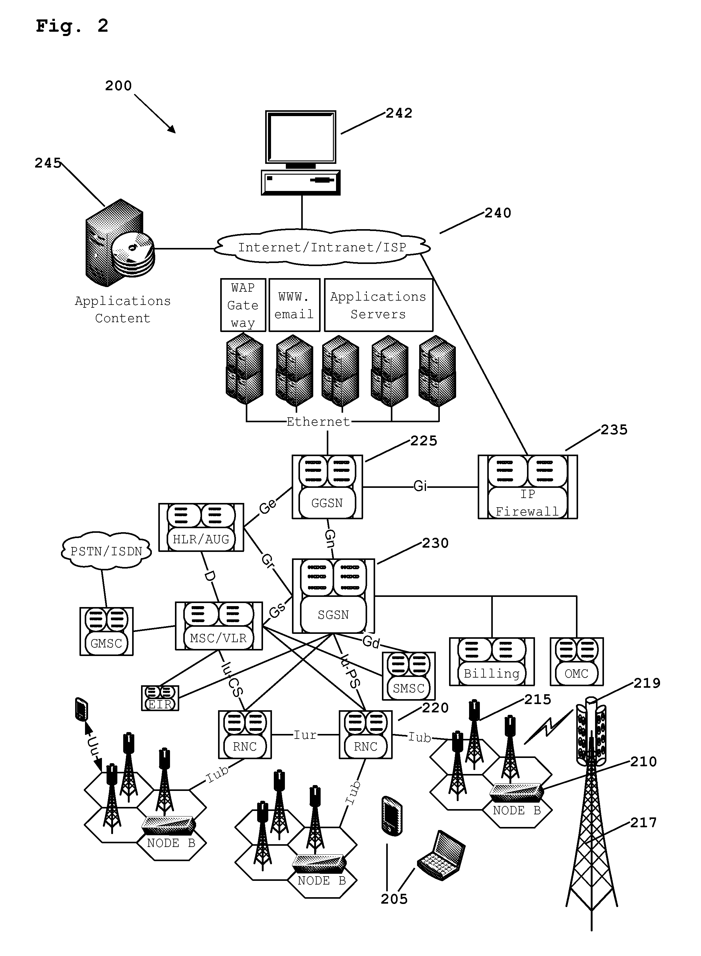
[0057]Many air interface standards exploit multiple access techniques using a common uplink or downlink carrier frequency. These include wideband code division multiple access (WCDMA) and orthogonal frequency division multiplexing (OFDM) based air interface protocols. As a result, multiple users may access the same Node B base station simultaneously. In existing systems, discerning angular user density using an antenna array and beam-forming system is not practical since a full demodulation process would be required for multiple narrow spatial beams. Furthermore, a demodulation only process would not help in the detection of interference sources within the sector. Embodiments of the invention employ a power scan method, where potential interference may be identified and spatially filtered prior to the demodulation process.

[0058]In contrast to known antenna array and beam-forming architectures, where only one beam (transmit or receive) is processed, embodiments of the invention utili...


PUM


Abstract

A wireless network element is operably couplable to an antenna array for communicating with at least one remote wireless communication unit. The antenna array comprises a plurality of radiating elements where at least one first radiating element of the plurality of radiating elements is arranged to create a radiation pattern in a sector of a communication cell. The wireless network element comprises a receiver arranged to receive and process at least one signal from the at least one remote wireless communication unit via the at least one first radiating element. The wireless network element also comprises a beam scanning module for stepping / sweeping the radiation pattern through the sector of the communication cell, such that at least one signal from the at least one remote wireless communication unit is processed to identify signal parameters representative of incoming signal power and angle of arrival of the received at least one signal.

Description

FIELD OF THE INVENTION[0001]The field of the invention relates to active antenna array control for use in a wireless communication system. In particular, the field of the invention relates to beam scanning using an antenna array to log user activity within a communication cell.BACKGROUND OF THE INVENTION[0002]Currently, 3rd generation (3G) cellular communication systems are being developed to further enhance the communication services provided to mobile phone UEs (user equipment). The most widely adopted 3rd generation communication systems are based on Code Division Multiple Access (CDMA) technology, namely Wideband Code Division Multiple Access (WCDMA). Carrier frequencies are used for uplink transmissions, i.e. transmissions from a mobile wireless communication unit (often referred to as wireless subscriber communication unit or UEs (in 3rd generation systems) to the communication infrastructure via a wireless serving base station (referred to as a Node B in 3rd generation system...

Claims


Application Information

Patent Timeline
IPC IPC(8): H04W24/00
CPCH01Q3/2605H01Q1/246
Inventor O'KEEFFE, CONORMOORE, JOE
Owner ANALOG DEVICES INT UNLTD
Learn More