Power factor correction circuit

a power factor and circuit technology, applied in the field of power factor correction circuits, can solve the problems of increasing radiation noise, increasing network loss, increasing high-frequency components over the entire high-frequency region, etc., and achieve the effect of increasing the maximum power consumption

Active Publication Date: 2012-08-09
ROHM CO LTD
View PDF9 Cites 29 Cited by
  • Summary
  • Abstract
  • Description
  • Claims
  • Application Information

AI Technical Summary

Benefits of technology

[0008]The present invention has been made in view of such a situation. Accordingly, it is an exemplary purpose of an embodiment of the present invention to provide a PFC circuit configured to be capable of suppressing an increase in the maximum power consumption due to an increase in the input electric power, and a control circuit thereof.
[0011]With such embodiments, when the amplitude of the AC voltage becomes large, the third voltage is increased in a stepwise manner according to an increase in the amplitude of the AC voltage. Thus, such an arrangement is capable of suppressing an increase in the amplitude of the fourth voltage due to an increase in the AC voltage. A feedback operation is performed such that the waveform that corresponds to a current that flows through the switching transistor matches the waveform of the fourth voltage. Thus, such an arrangement is capable of suppressing an increase in the maximum power consumption due to an increase in the amplitude of the AC voltage.
[0013]With the resistance values of the first resistor through the fourth resistor as R1 through R4, the fourth voltage is proportional to R3×R4 / (R1×R2). Thus, even if the resistance values of the first resistor through the fourth resistor fluctuate at the same rate due to temperature fluctuation, process variation, or the like, such an arrangement is capable of reducing the effects of such fluctuation on the fourth voltage, thereby improving the temperature characteristics of the PFC circuit.
[0019]Such an arrangement is capable of suppressing a rise in the output voltage of the DC / DC converter.
[0021]Such an arrangement is capable of reducing the effects of a sharp change in the load of the DC / DC converter.

Problems solved by technology

Such current pulses lead to problems of increased radiation noise, increased network loss, and increased high-frequency components over the entire high-frequency region.

Method used


Image

  • Power factor correction circuit
  • Power factor correction circuit
  • Power factor correction circuit

Examples


first embodiment

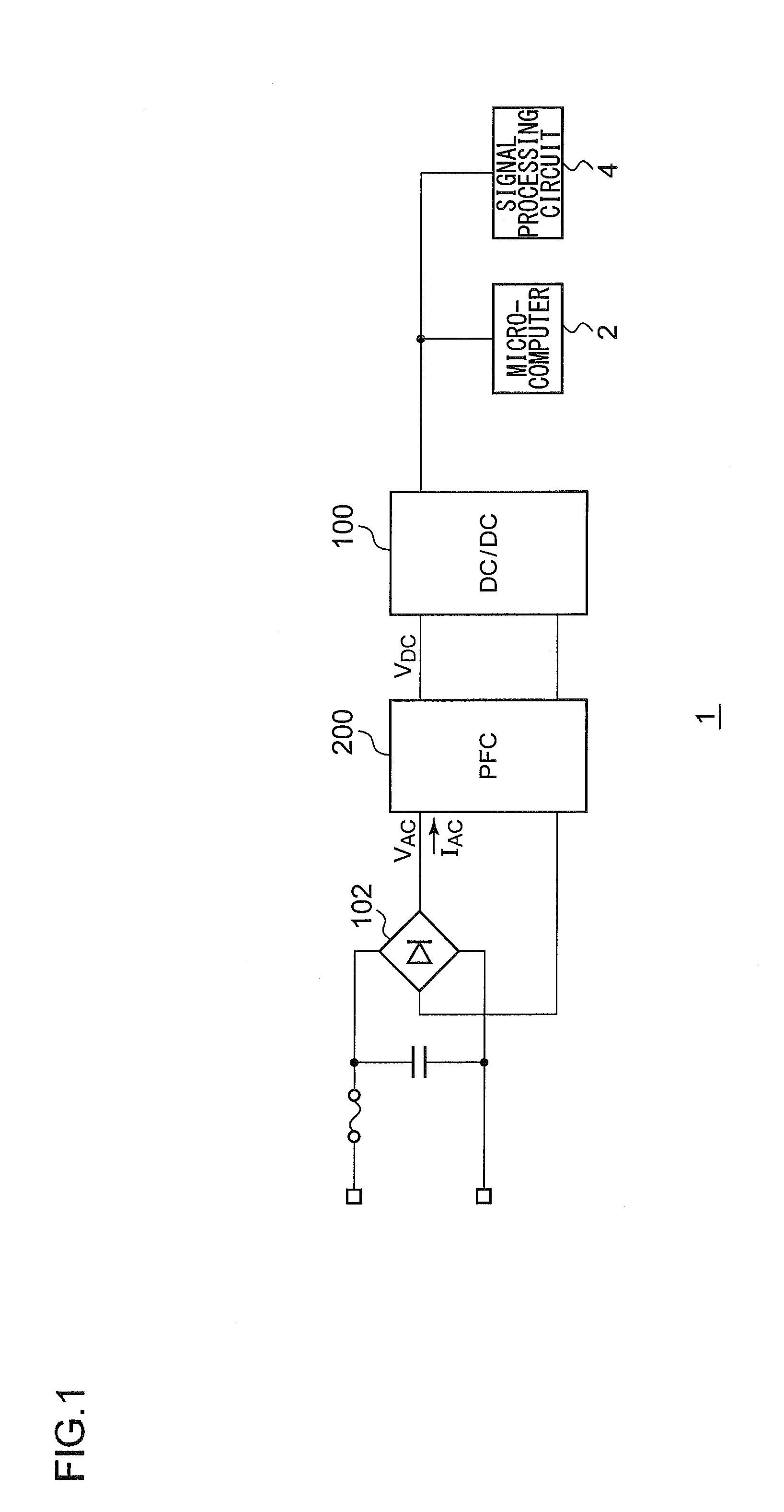
[0041]FIG. 1 is a circuit diagram which shows a configuration of an electronic device 1 according to an embodiment.

[0042]The electronic device 1 is configured as a consumer electronics device such as a TV, refrigerator, air conditioner, or the like, or otherwise as a computer. The electronic device 1 includes a microcomputer 2, a signal processing circuit 4, a DC / DC converter 100, a rectifier circuit 102, and a PFC (power factor correction circuit) 200. The electronic device 1 is partitioned into a primary side and a secondary side that are electrically insulated from each other by means of an insulating transformer (not shown) of the DC / DC converter 100.

[0043]The rectifier circuit 102 is configured as a diode rectifier circuit, for example, and is configured to receive an AC voltage such as commercial AC voltage or the like, and to perform full-wave rectification of the AC voltage thus received so as to generate an AC voltage VAC.

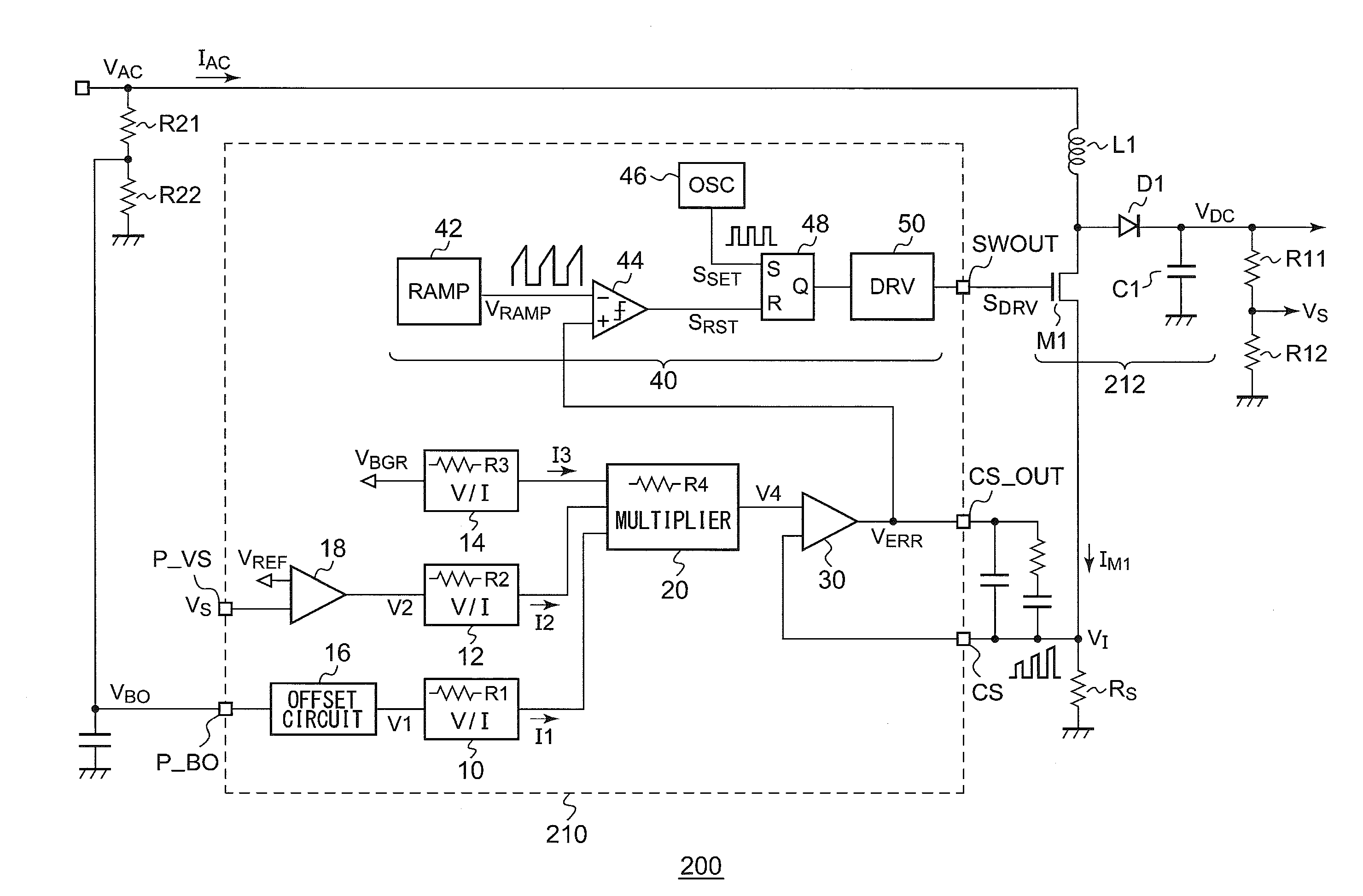
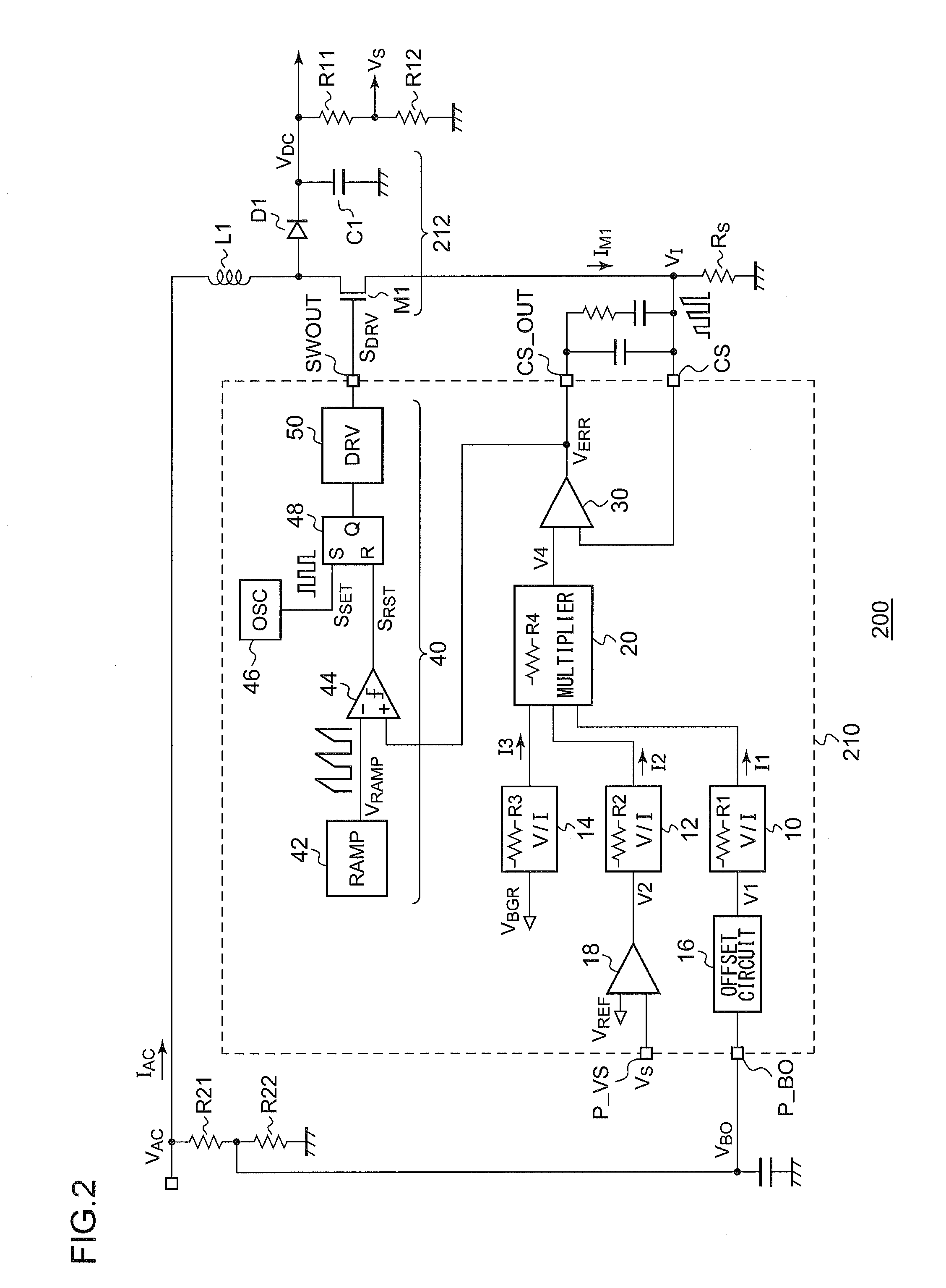
[0044]The PFC circuit 200 is configured as a step-up...

second embodiment

[0112]Description has been made in the first embodiment regarding a technique for improving the temperature characteristics. Description will be made in a second embodiment regarding a technique for suppressing an increase in the maximum power consumption due to an increase in the input electric power of the PFC circuit, according to a combination of the first embodiment and the second embodiment, or otherwise according to the second embodiment alone.

[0113]FIG. 7 is a circuit diagram which shows a configuration of a PFC circuit 200c including a control circuit 210c according to the second embodiment. A peripheral circuit of the control circuit 210c has the same configuration as that shown in FIG. 6, and accordingly, description thereof will be omitted. It should be noted that the peripheral circuit of the control circuit 210c may be configured in the same way as shown in FIG. 5.

[0114]Description will be made below regarding a specific configuration of the control circuit 210c. The c...


PUM


Abstract

A first error amplification circuit amplifies a difference between a predetermined reference voltage and a first detection voltage that corresponds to the output voltage of a DC / DC converter, so as to generate a second voltage. A voltage level judgment circuit generates a third voltage having a discrete level that corresponds to the amplitude of a first voltage. A multiplying / dividing circuit multiplies the first voltage by the second voltage, and divides the resulting product by the third voltage, so as to generate a fourth voltage. A comparator compares the fourth voltage with a second detection voltage that corresponds to a current that flows through a switching transistor included in the DC / DC comparator. A driving circuit turns on the switching transistor for each predetermined period, and turns off the switching transistor according to the output of the comparator every time the second detection voltage becomes higher than the fourth voltage.

Description

BACKGROUND OF THE INVENTION[0001]1. Field of the Invention[0002]The present invention relates to a power factor correction circuit employing a DC / DC converter.[0003]2. Description of the Related Art[0004]Various kinds of consumer electronics devices such as TVs, refrigerators, etc., or otherwise electronic devices such as laptop computers, cellular phone terminals, and PDAs (Personal Digital Assistants), are each configured to operate receiving electric power from an external circuit, and to be capable of charging a built-in battery using electric power received from an external power supply. Such consumer electronics devices and electronic devices (which will collectively be referred to as “electronic devices” hereafter) each include a built-in power supply apparatus configured to perform AC / DC conversion of commercial AC voltage. Alternatively, such a power supply apparatus is configured as a built-in component included within an external power supply adapter (AC adapter) for such...

Claims


Application Information

Patent Timeline
Patent Type & Authority Applications(United States)
IPC IPC(8): H02M7/06G05F1/70
CPCY02B70/126H02M1/4225Y02B70/10
Inventor NATE, SATORUSATO, YOSHINORI
Owner ROHM CO LTD
Why Eureka
Try Eureka