

Layered product for laser bonding, shoe, and process for producing shoe
a laser bonding and product technology, applied in the field of laminates, can solve the problems of poor bonding, easy deformation of foam on the surface, and easy deformation of foam on the surface, and achieve the effect of improving the bonding
- Summary
- Abstract
- Description
- Claims
- Application Information
AI Technical Summary
Benefits of technology
Problems solved by technology
Method used
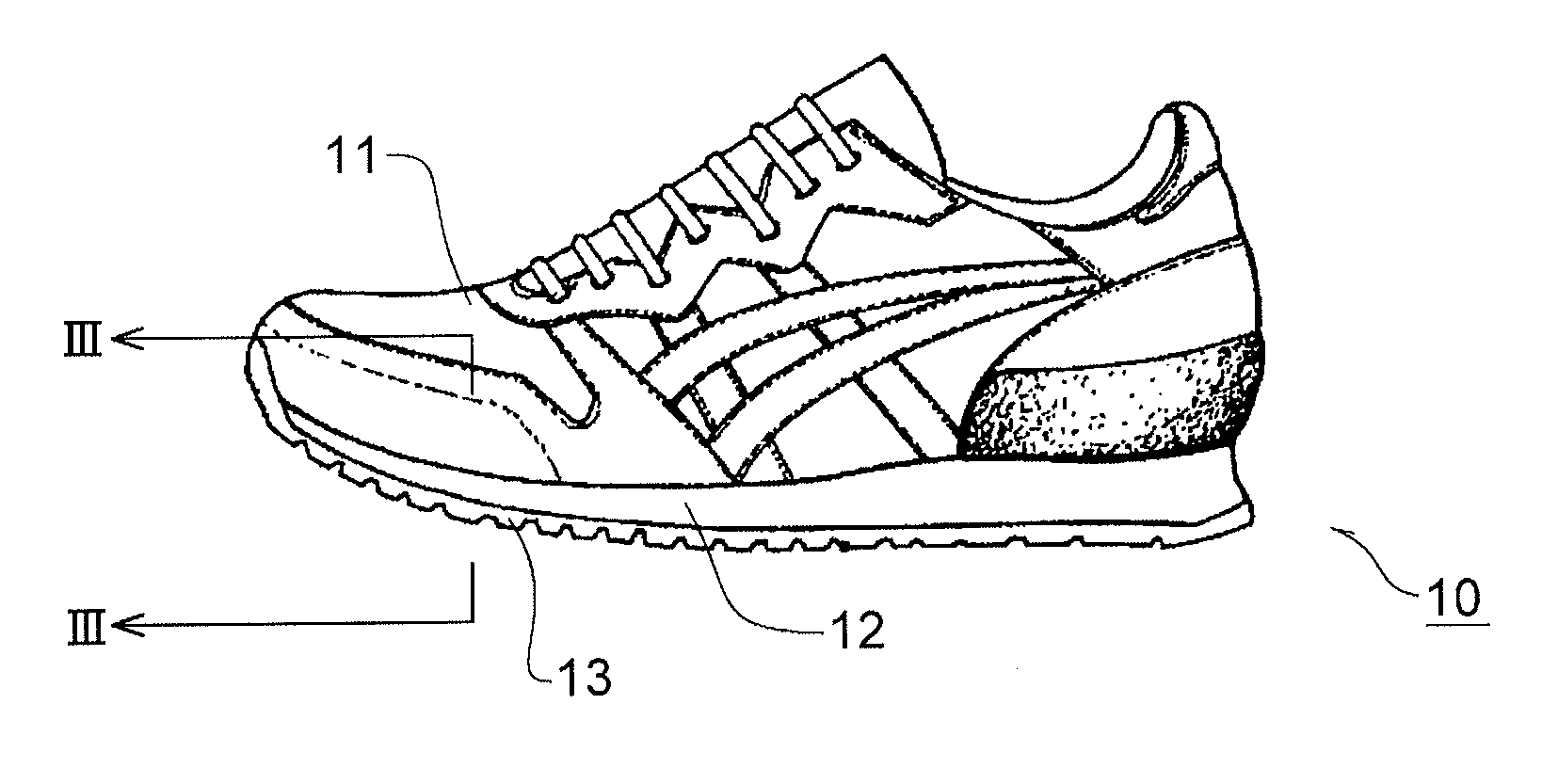
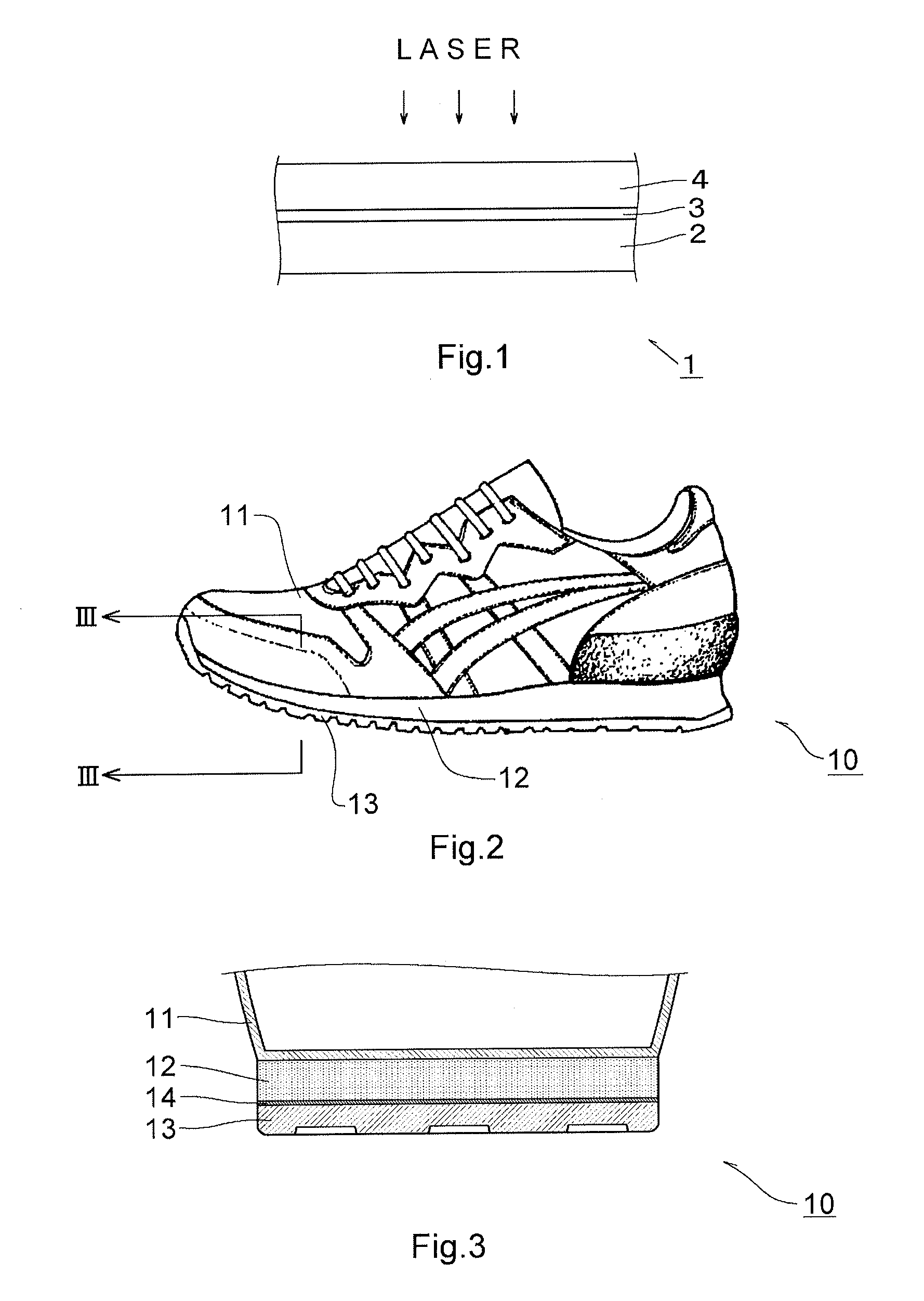
Image

Examples
example
[0131]The present invention will be further described in detail below with reference to Examples and Comparative Examples. Here, the present invention is not limited only to the following Examples.
[Materials Used for Examples and Comparative Examples]
(A) First Member (Foam)
Foam (1):
[0132]A foam consisting of a mixture of 100 parts by mass of low density polyethylene (product name “PETROSEN 170” manufactured by Tosoh Corporation; specific gravity 0.92; MFR 1.0 g / 10 minutes), 2.5 parts by mass of a foaming agent (product name “AC#3C-K2” manufactured by EIWA CHEMICAL IND. CO., LTD.), 0.6 part by mass of a crosslinker (product name “PERCUMYL D” manufactured by NOF CORPORATION), 0.5 part by mass of a processing aid (stearic acid manufactured by New Japan Chemical Co., Ltd.), and 1 part by mass of zinc oxide (manufactured by Honjo Chemical Corporation).
[0133]The mixture was kneaded using a kneader, and then pressed at 160° C. at a pressure of 15 MPa for about 20 minutes using a pressing m...
examples 1 to 23
[0184]A laminate of Example 1 was prepared by laminating the sheet (1) on the foam (1).
[0185]As shown in Table 2, laminates of Examples 2 to 23 were prepared in the same manner by laminating the forms and the sheets, respectively.
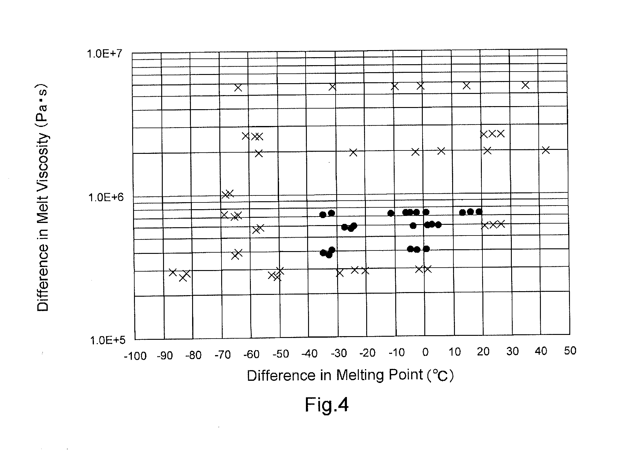
TABLE 2Difference ofDifference ofFirst MemberMelting PointMelt VisocityConditions after(Foam)Bonding Sheet(° C.)(Pa · s)DelaminationExample 1Foam (1)Sheet (1)−3.6585266material ruptureExample 2Foam (1)Sheet (2)1.4596995material ruptureExample 3Foam (1)Sheet (3)2.9598431material ruptureExample 4Foam (1)Sheet (5)−27.2579806material ruptureExample 5Foam (1)Sheet (6)−24.1597770material ruptureExample 6Foam (1)Sheet (10)5.2593152material ruptureExample 7Foam (2)Sheet (3)−4.6402361material ruptureExample 8Foam (2)Sheet (5)−34.7383735material ruptureExample 9Foam (2)Sheet (6)−31.6401700material ruptureExample 10Foam (2)Sheet (10)−2.3397082material ruptureExample 11Foam (2)Sheet (11)1.0402253material ruptureExample 12Foam (3)Sheet (1)−11.1718895material ruptureExam...
examples 24 to 31
[0203]As shown in Table 5, laminates of Examples 24 to 31 were prepared in the same manner by laminating the forms and the sheets, respectively.
TABLE 5FirstDifferenceDifference ofMelt ViscosityMemberBondingof MeltingMelt Visocityof BondingConditions after(Foam)SheetPoint (° C.)(Pa · s)Sheet (Pa · s)DelaminationExample 24Foam (7)Sheet (2)−9.010374421472material ruptureExample 25Foam (7)Sheet (3)−7.5103887736material ruptureExample 26Foam (7)Sheet (6)−34.51038217697material ruptureExample 27Foam (7)Sheet (11)−1.91038769144material ruptureExample 28Foam (8)Sheet (2)1.525870541472material ruptureExample 29Foam (8)Sheet (3)3.0258848936material ruptureExample 30Foam (8)Sheet (6)−24.02587829697material ruptureExample 31Foam (8)Sheet (11)8.62588381144material rupture
PUM
| Property | Measurement | Unit |
|---|---|---|
| melting point | aaaaa | aaaaa |
| melt viscosity | aaaaa | aaaaa |
| melt viscosity | aaaaa | aaaaa |
Abstract
Description
Claims
Application Information