Method and device for determining a maximum leakage current

a leakage current and maximum technology, applied in the direction of testing circuits, instruments, impedence measurements, etc., can solve the problems of potentially lethal leakage current flow in closed circuits, fatal consequences for patients, and impair the action of medical measures, so as to increase reliability and reduce the frequency of triggering

Active Publication Date: 2012-08-16
BENDER SA
View PDF8 Cites 11 Cited by
  • Summary
  • Abstract
  • Description
  • Claims
  • Application Information

AI Technical Summary

Benefits of technology

[0015]The present invention is therefore based on the object of developing a method and also a device for determining the maximum leakage current, which increases the reliability in t

Problems solved by technology

In practice, however, the mains have finite ohmic and capacitive resistances—a complex-valued network leakage impedance—with respect to earth, so that in the event that a conductor becomes connected to earth potential by means of touching an (earthed) person, a closed circuit results via this network leakage impedance and the human body, in which closed circuit potentially lethal leakage currents can flow.
An additional current flow, which is brought about unintentionally, could impair the action of the medical measure and, in the worst case scenario, have fatal consequences for the patient.
Whilst the determination of the network voltage for the most part results from a conventional voltage measurement by means of a resistor network and does not place any great demands on measurement technology, the determination of the complex-valued network impedance ZE shapes up to be complex, as a suitab

Method used


Image

  • Method and device for determining a maximum leakage current
  • Method and device for determining a maximum leakage current
  • Method and device for determining a maximum leakage current

Examples


Embodiment Construction

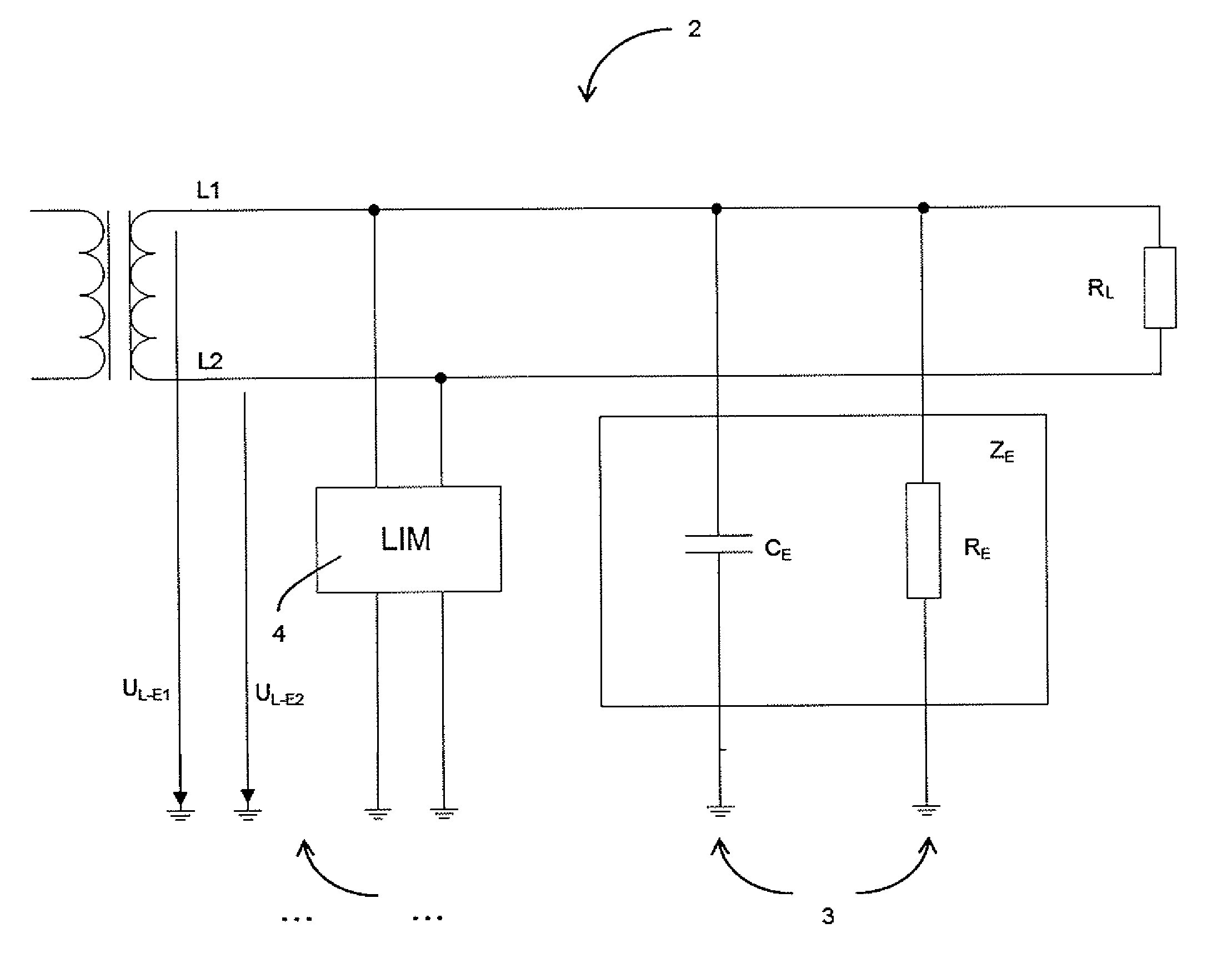
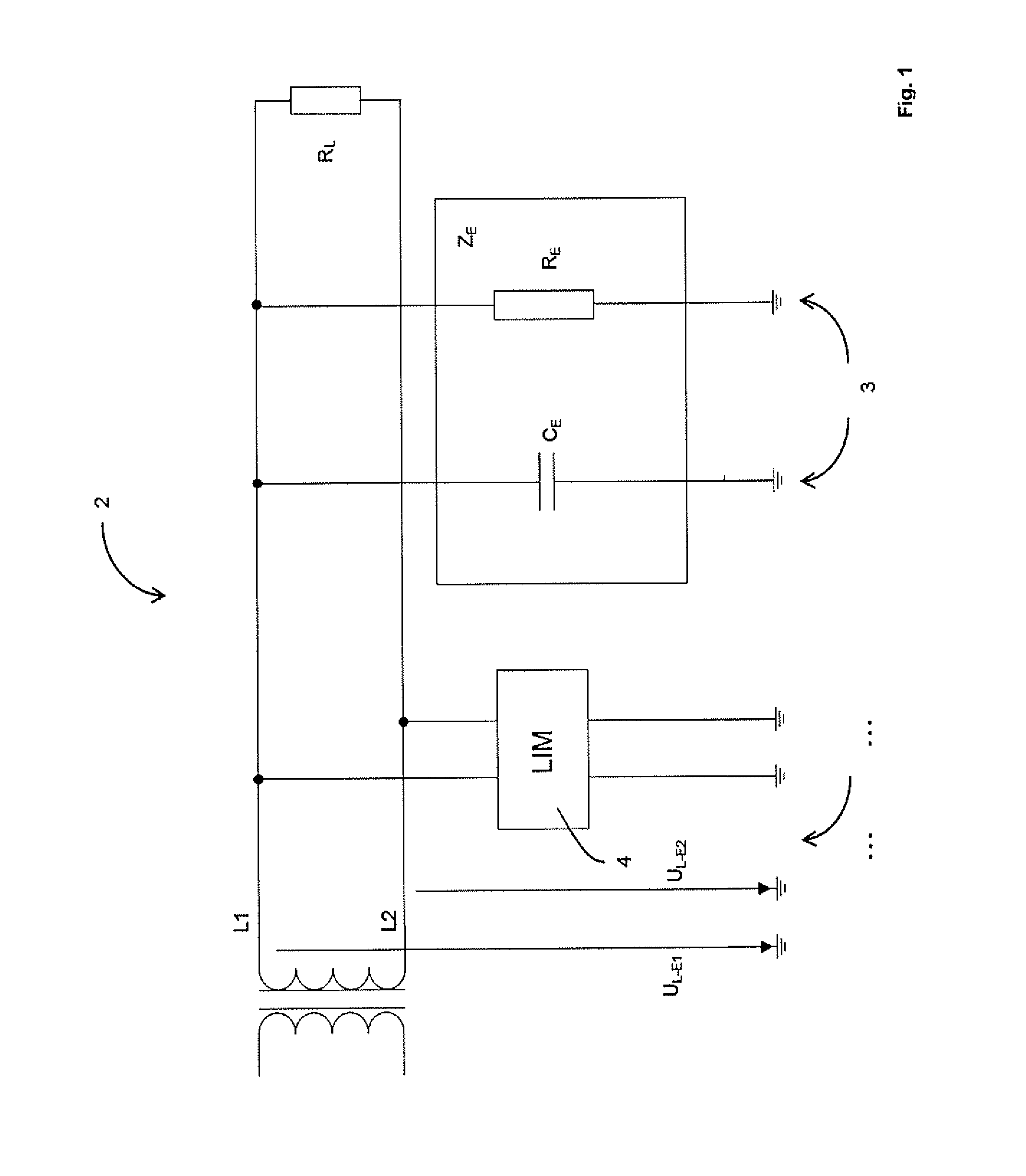
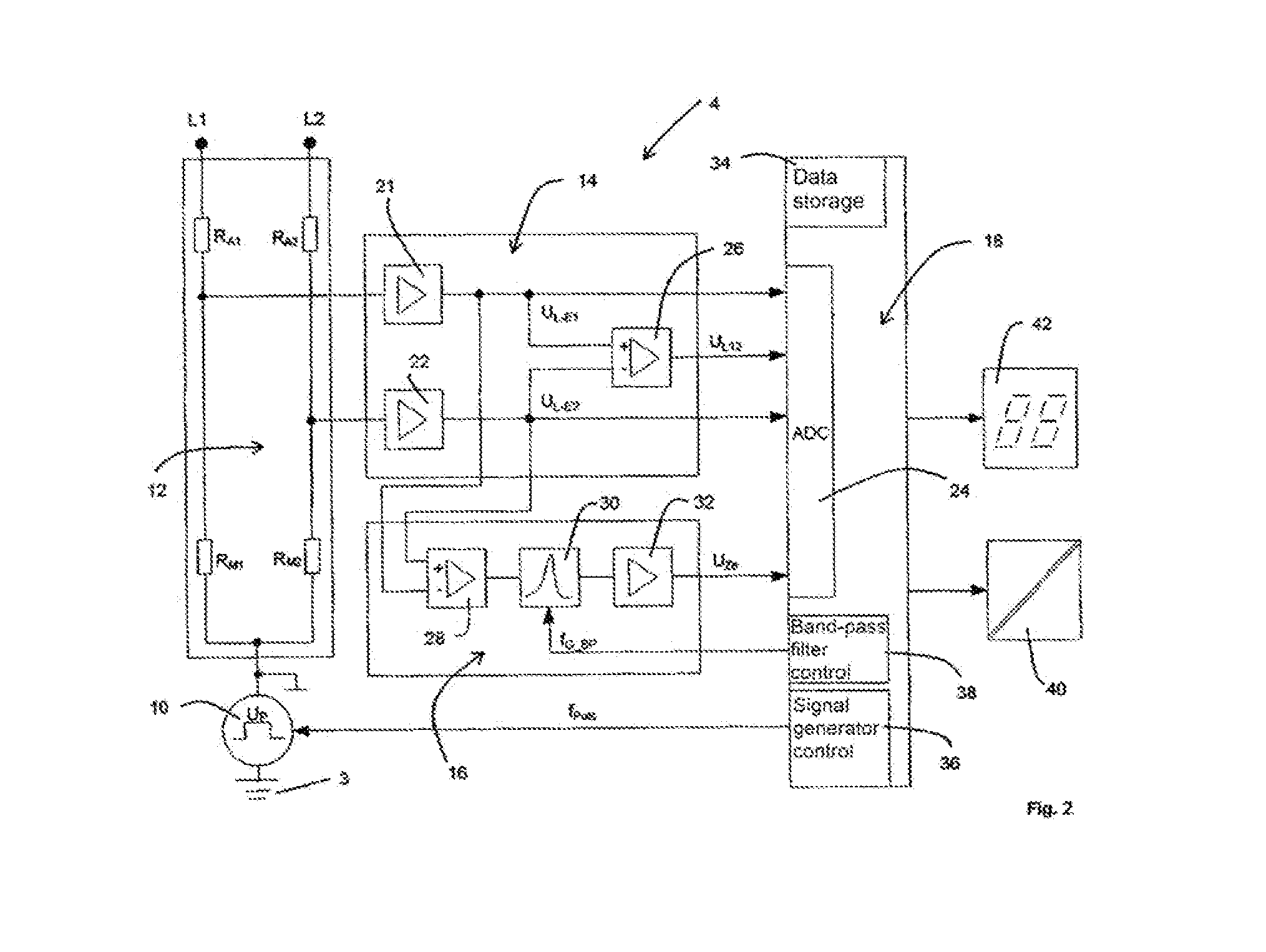
[0049]In the following, the background of the invention including the relevant circuit values is initially presented in FIGS. 1 to 3, starting from an embodiment of the device according to the invention. The FIGS. 4 and 5 relate to an embodiment of the method according to the invention.

[0050]FIG. 1 shows a block diagram of an unearthed power supply network 2 with two active conductors L1, L2, as is used everywhere where operational safety and personal protection is a priority. For example, mains of this type for energy supplying of medical devices, shown by means of the load RL, could be used in hospitals. Neither of the two active conductors L1 and L2 is connected to the earthed potential 3 (the impedance ZE may initially be ignored), so that a closed current path does not arise in the case of the touching of a conductor by an (earthed) person. On the one hand, the person is protected from unacceptably high body currents by means of this arrangement, so that personal protection is ...


PUM


Abstract

The invention relates to a method and a device for determining a maximum leakage current in unearthed power supply networks with a plurality of conductors. The method comprises the steps of: feeding of a measurement signal UP with a measurement frequency fPuls into a conductor arrangement, setting the measurement frequency fPuls, measuring a line-to-line voltage UL-E for each conductor, determining a maximum occurring line-to-line voltage UL-Emax from the measured line-to-line voltages UL-E, determining a voltage UZe across a measurement resistance RM for calculating a leakage impedance ZE, calculating the leakage impedance ZE, and calculating a maximum leakage current THC. The device comprises a signal generator for feeding in the UP with the fPuls, a network coupling circuit between the signal generator and the conductor arrangement, a voltage measuring circuit for measuring the UL-E, and an impedance measuring circuit for determining the Ze by means of the determining of the UZe.

Description

FIELD OF THE INVENTION[0001]The invention relates to a method for determining a maximum leakage current in unearthed power supply networks with a plurality of live conductors.[0002]Furthermore, the invention relates to a device for determining a maximum leakage current in unearthed power supply networks with a plurality of live conductors.BACKGROUND OF THE INVENTION[0003]When designing a power supply system, in addition to the performance of the power network, operational and personal safety must be ensured. A protective concept for a faultless operation therefore comprises protective measures which ensure continuous power supply with simultaneous personal and plant protection.[0004]Unearthed mains have proven themselves with regards to operational safety and the minimisation of the risk of unavailability of the power supply. In unearthed mains, there are no active conductors directly connected to earth potential, so that in the event of a (unipolar) earth fault, in the absence of a...

Claims


Application Information

Patent Timeline
IPC IPC(8): G01R27/18
CPCG01R27/18G01R31/025G01R31/3008G01R31/52
Inventor SCHAEFER, OLIVER
Owner BENDER SA
Why Eureka
Try Eureka