Magneto-optical device with an optically induced magnetization

a technology of optical induced magnetization and magnetic transducer, which is applied in the field of magnetic transducer, can solve the problems of unidirectional anisotropy, excessive labor, and complex labor-consuming procedures

Active Publication Date: 2012-08-16
KATSNELSON ESFIR Z +1
View PDF5 Cites 7 Cited by
  • Summary
  • Abstract
  • Description
  • Claims
  • Application Information

AI Technical Summary

Problems solved by technology

A fabrication of the conventional FM / AFM element with an exchange coupling, which results in the unidirectional anisotropy, involves a number of complex labour consuming procedures.
A great number of complex procedures lead also to an excessive labour and thus a production costs.
Therefore manufacturing conventional bias elements requires a utilization of alloys with expensive noble metals (for example, such as PtMn and IrMn and Ta as protective layer) with excessive production procedures.
The fabrication of conventional exchange bias elements involves an essential difficulty when successive layers of the read head should be biased in different directions.
Therefore for the second (or third) pair of layers (free and fixed), manufacturing the conventional magnetic bias element involves additional and thus costly fabrication procedures such as resetting, which refreshes the direction of the bias field in the hard bias layer (Wang et al., U.S. Pat. No. 7,230,845).
Aforesaid leads to additional labour expenses with a price increase.
The longitudinal recording is accompanied with complicated processes and calculations.
As result, the recording into very small bits is hampered.
These calculations became even more complicated because, at the same time, demagnetizing fields oppose the magnetization and can destroy recorded patterns of magnetization.
This disadvantage leads to the problem of noise from the SUL because of the domain formation.
An appearance of domain walls generates strong magnetic fields, which cause a strong noise during reading.
A combination of the single pole and SUL leads to erasure problems.
A stray field of 3 Oe is harmful for a drive.
This interaction can reduce the coercivity of the recording layer and produce a large noise during the readout.
However this leads to a deterioration of the thermal stability factor.
A thermal magnetic hysteresis of a magnetic permeability, which is caused by heating and cooling, irreversibly changes magnetic properties of the magnetic medium.
An increase in writing power, which is necessary at a desensitization of the media, leads to a degradation of the media and shortening a media lifetime.
Latter complicates recording process and reduces recording speed.
A necessity of simultaneous usage of the magnetic field and an optical wave leads to a complex drive system.
Expensive rare-earth metals, which should be doped with Cr and coated with Si—N layers from corrosion, complicate the fabrication and increase the cost of MO materials.
A readout of magneto-optically recorded marks is also very complicated and protracted process (Masahiko Kaneko, “Material for Magneto-Optical Recording”, MRS Bulletin, vol.
After carrying out a number of heat-cooling operations, the recording medium will irreversibly change magnetic properties due to temperature magnetic hysteresis and become degraded chemically.

Method used


Image

  • Magneto-optical device with an optically induced magnetization
  • Magneto-optical device with an optically induced magnetization
  • Magneto-optical device with an optically induced magnetization

Examples


first embodiment

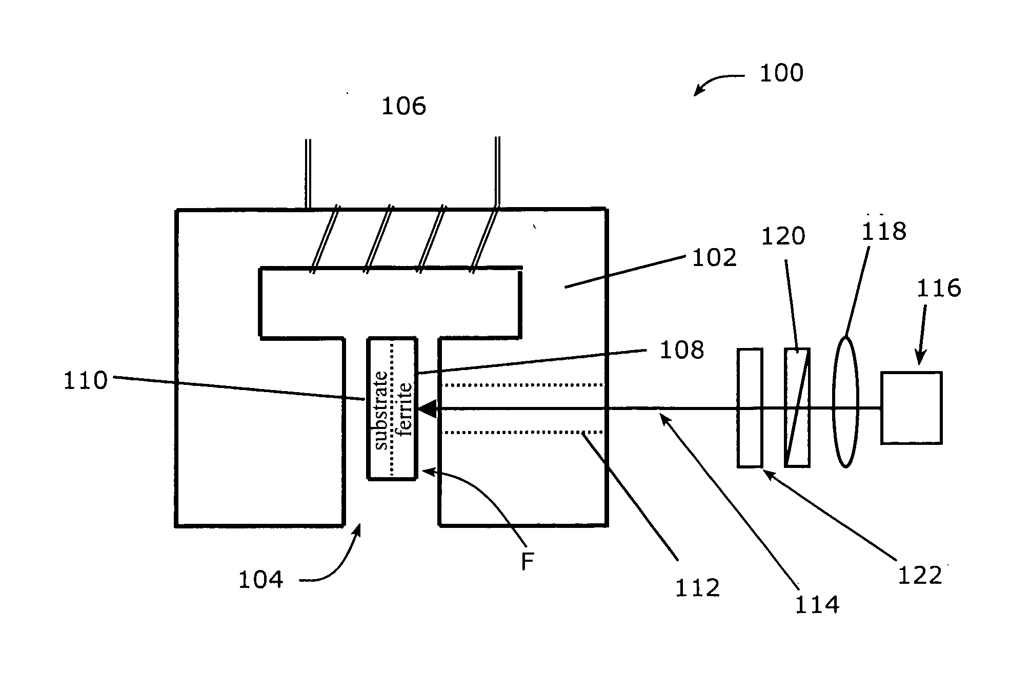
[0097]A first embodiment is shown in FIG. 3 and is generally designated therein by the reference numeral 100 and illustrates a method for producing a magneto-optical element with an optically induced magnetization or the magneto-optical device (MOD) with a unidirectional anisotropy at room temperature as well as a scheme of illumination at a magnetic field.

[0098]A system comprises an electromagnet, the MOD, and a system for illumination. The electromagnet contains a soft ferromagnetic yoke 102 with two poles, a gap 104 between the poles, and a conductor 106 wrapped around the yoke 102 as a coil or winding structure. An electrical current passing through conductor 106 creates a magnetic field H about of 3 kOe. The MOD comprises a Mg—Mn—Co— ferrite film 108 deposited on a MgO substrate 110. The MOD is located in the gap 104 between the poles, with the ferrite film 108 parallel to pole surfaces. The ferrite film 108 is illuminated through an opening 112 in one of the poles of the yoke ...

second embodiment

[0129]A second embodiment is shown in FIG. 4 and is generally designated therein by the reference numeral 200. As shown, the magneto-optical device 200 with the optically induced magnetization in the ferrimagnetic ferrite film can be used as a biasing or pinning magnetization (of FM layers) element in magnetoresistive read heads and in a tip of a needle of the magnetic force microscope (MFM) using the optically induced magnetization (OIM), which is stable to a conventional ac demagnetization and has an indefinitely long relaxation time.

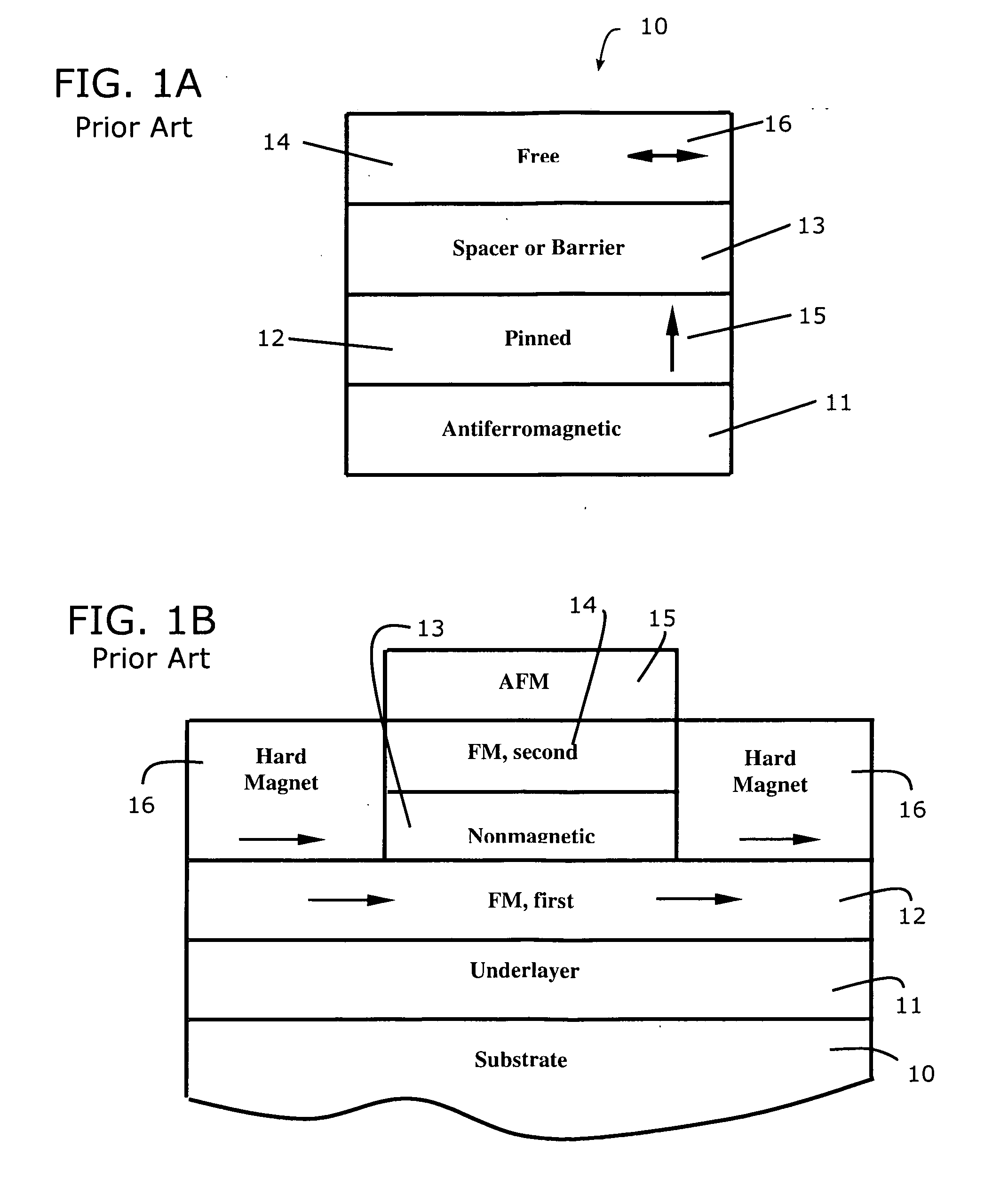
[0130]FIG. 4 shows a simplified scheme of the magneto-resistive sensor, which is improved by using the magneto-optical device (MOD) in accordance with the second embodiment. The MOD can replace elements pinning magnetization of FM layers, for example, in a conventional MR sensor, shown in FIG. 1B (also described by Dieny et al. in U.S. Pat. No. 5,206,590 and shown in FIG. 5 herein). In FIG. 1B, the MOD can replace antiferromagnetic layer 15 (which for...

third embodiment

[0142]A method and system for magneto-optical recording using the MOD as a memory cell is presented in a third embodiment.

[0143]FIG. 6 shows a simplified scheme of a magneto-optical recording system designed in accordance with the third embodiment and is generally designated therein by the reference numeral 300. As shown, the system comprises a soft FM yoke 302 with two poles, the MOD, which is used as a recording medium with a patterned Mg—Mn—Co-ferrite film 304 deposited on the MgO substrate 306, which can be part of a disk structure. As the disk with the recording medium moves through a gap 308, a portion of the surface F of the ferrite film 304 is illuminated through an opening 310 in one of the poles (unnumbered) of the yoke 302. A conductor 312 is wrapped around the yoke 302 to form a coil or winding structure. A current, passing through conductor 312, creates the magnetic field H about of 3 kOe. A laser beam 314 from a laser diode 316 (for example, with a wave length of 632.8...


PUM

PropertyMeasurementUnit
superparamagnetic sizeaaaaaaaaaa
magnetizationaaaaaaaaaa
relaxation timeaaaaaaaaaa

Abstract

A magneto-optical device (MOD) with optically induced magnetization for use in magnetic field sensors as a magnetic element pinning a magnetization in a preferred direction of a ferromagnetic layer as well as a magnetic memory cell for magneto-optical recording. The MOD comprises the Mg—Mg—Co ferrite film deposited on a magnesium oxide (MgO) substrate. The ferrite film is illuminated at room temperature with a circularly polarized light (CPL) in a static magnetic H-field (about of 3 kOe) normal to the illuminated ferrite film surface. At certain (“writing”) combinations of H, sigma (CPL helicity), the long-lived optically induced magnetization with a unidirectional anisotropy, stable to a conventional demagnetization occurs. For readout of information, conventional magnetoresistive sensors and MFM can be used. To erase information, the ferrite film should be illuminated with two field-light combinations, other than “writing”, or annealed at temperature higher than 530 degrees C.

Description

CROSS-REFERENCE TO RELATED PATENT APPLICATION[0001]This patent application is a continuation of earlier-filed U.S. patent application Ser. No. 12 / 929,879 filed Feb. 23, 2011 by the inventors herein and claims the benefit of earlier-filed U.S. Provisional Patent Application 61 / 339,122, filed Mar. 1, 2010 by the inventors herein, the disclosure of which is incorporated herein by reference.TECHNICAL FIELD [0002]The patent application relates in general to magneto-optical devices (MODs), which involve new magnetic properties created and changed by light, but up to now not realized in magnetic materials. New magnetic properties comprise an optically induced magnetic memory with an indefinitely long relaxation time, the long-lived optically induced unidirectional anisotropy, and an optically induced increase in the Curie temperature. New photo-induced magnetic properties allow the data to be written, stored and reproduced. A magneto-optical memory based on the optically induced magnetizat...

Claims


Application Information

Patent Timeline
Patent Type & Authority Applications(United States)
IPC IPC(8): G11B13/04G01Q60/50G02F1/09
CPCG11B5/02G11B5/3932G11B5/70678G11C13/06G11B13/045G11B2005/0002G11B5/74
Inventor KATSNELSON, ESFIR Z.CHERVINSKY, MARK M.
Owner KATSNELSON ESFIR Z
Why Eureka
Try Eureka