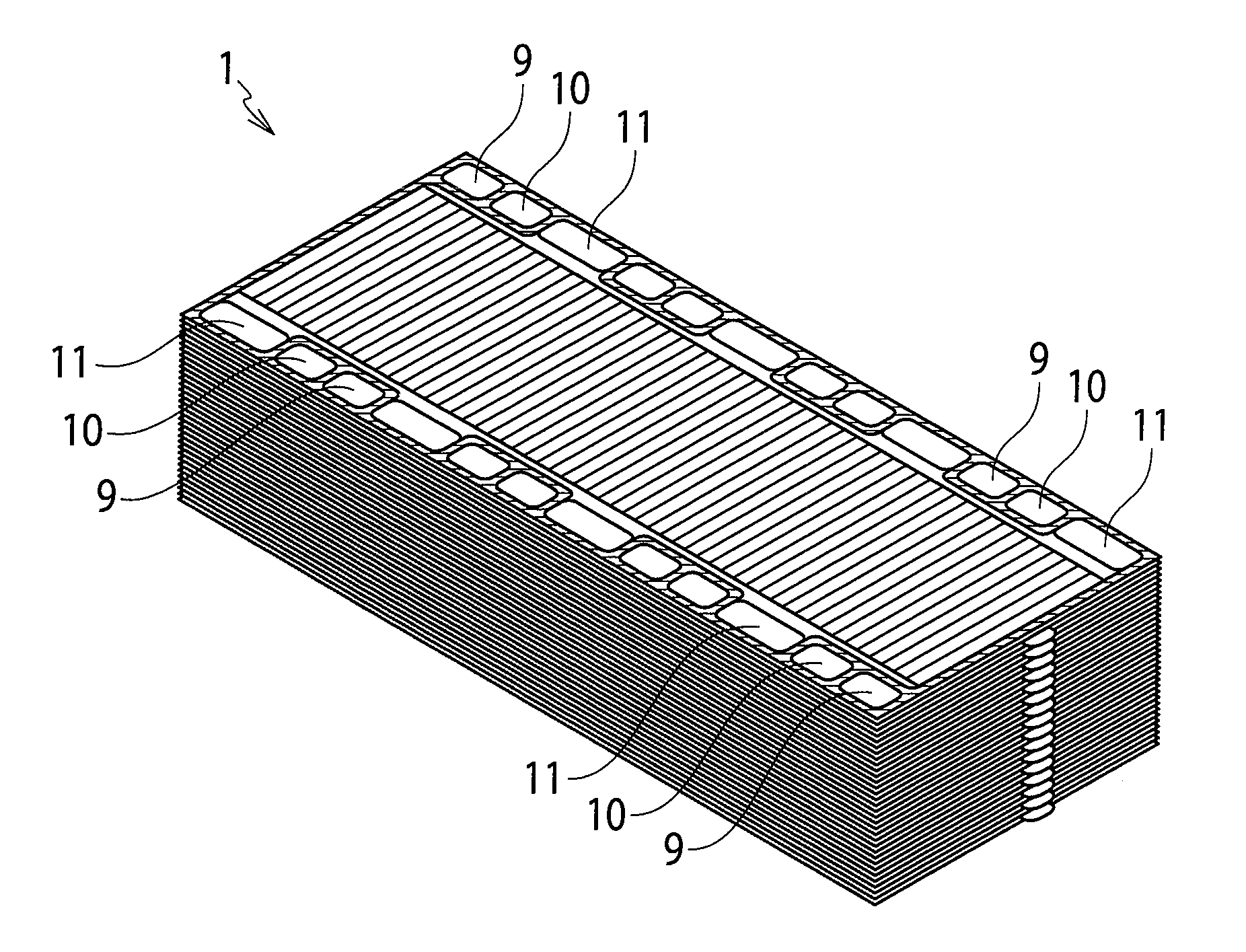
Fuel cell and vehicle including the fuel cell

a fuel cell and vehicle technology, applied in the field of fuel cells and vehicles including fuel cells, can solve the problems of predetermined pressure loss, excessive pressure loss, and limitations on the miniaturization of conventional fuel cells, and achieve the effects of improving vehicle mountability, productivity and cost, and improving volumetric power density

Active Publication Date: 2012-08-30
NISSAN MOTOR CO LTD
View PDF5 Cites 8 Cited by
  • Summary
  • Abstract
  • Description
  • Claims
  • Application Information

AI Technical Summary

Benefits of technology

[0009]Incidentally, in order to use the fuel cell as the power supply of an automobile and the like, the fuel cell is required to be further miniaturized for the purpose of improving vehicle mountability, productivity and cost. Then, in order to improve the volumetric power density by means of the same catalyst area, it is effective to thin the single cell of the fuel cell.

Problems solved by technology

However, for the conventional typical fuel cell, such a flow passage design that causes a predetermined pressure loss is made since the water produced following the power generation is removed by flows of hydrogen and air.
Therefore, when the thickness of the single cell of the fuel cell is simply reduced for the purpose of the miniaturization, the pressure loss becomes excessive, and loads on a variety of fluid supply devices necessary for drive of the fuel cell are increased, and accordingly, there are limitations on the miniaturization in the conventional fuel cell.
However, in the case where the long side and short side of each separator are in this ratio, if the depth of the flow passage is reduced, and the thickness of the single cell of the fuel cell is thinned, then the pressure loss becomes excessive.

Method used


Image

  • Fuel cell and vehicle including the fuel cell
  • Fuel cell and vehicle including the fuel cell
  • Fuel cell and vehicle including the fuel cell

Examples


example 1

[0088]First, 5 parts (carbon average particle diameter: approximately 3 μm) of Acetylene Black made by Denki Kagaku Kogyo Kabushiki Kaisha and 1 part of Polyflon D-1E made by Daikin Industries, Ltd. were mixed with each other, whereby ink slurry was prepared. Next, the above-described ink slurry was coated on Carbon Paper TGP-H-060 made by Toray Industries, Inc., followed by baking at 350° C., whereby a GDL having a carbon particle layer on a surface thereof was created. A thickness of the obtained GDL was 0.2 mm, and a shape of the GDL was a rectangle with a width 595 mm×a length 52 mm.

[0089]Next, catalyst layers containing platinum-supported carbon were coated on both surfaces of an electrolyte membrane (polymer electrolyte membrane Nafion 211 made by DuPont Corporation), whereby a CCM was created. A shape of the CCM was a rectangle with a width 606 mm×a length 88 mm. A shape of the catalyst layers was a width 593 mm×a length 50 mm. That is to say, an aspect ratio R of the catalys...

example 2

[0096]First, the membrane electrode assembly of Example 1 was cut out to a size of a width 50 mm×a length 50 mm. Moreover, by using the separators of Example 1, the flow rates of the fuel gas and the oxidant gas were also set at a 50 (mm) / 593 (mm) time that of Example 1. In such a way, the sub-scale fuel cell (aspect ratio R=1) of Example 2 was created.

example 3

[0102]Evaluation of power generation in Example 3 was performed by using the fuel cell of Example 2 and setting operation conditions as follows. Specifically, the stoichiometric ratio was set at 1.6 (anode) and 1.5 (cathode), inlet relative humidity was set at non-humidification (anode) and 20% RH (cathode), and an operation pressure was set at 200 kPa (absolute pressure). Moreover, thicknesses of the Carbon Paper serving as the gas diffusion layers and of the electrolyte membrane were set at 80 μm and 15 μm, respectively. The power generation characteristics were evaluated by a similar method to that of Example 2 other than the above.

[0103]Note that, when the Carbon Paper with a thickness of 80 μm was used in the fuel cell of Comparative example 1, since the channel width was wide (channel width: 1 mm) therein, the Carbon Paper was broken at a rib edge, the electrolyte membrane was damaged, and a short circuit occurred. As opposed to this, in the fuel cell of Example 3, such a shor...


PUM

PropertyMeasurementUnit
thicknessaaaaaaaaaa
heightaaaaaaaaaa
heightaaaaaaaaaa

Abstract

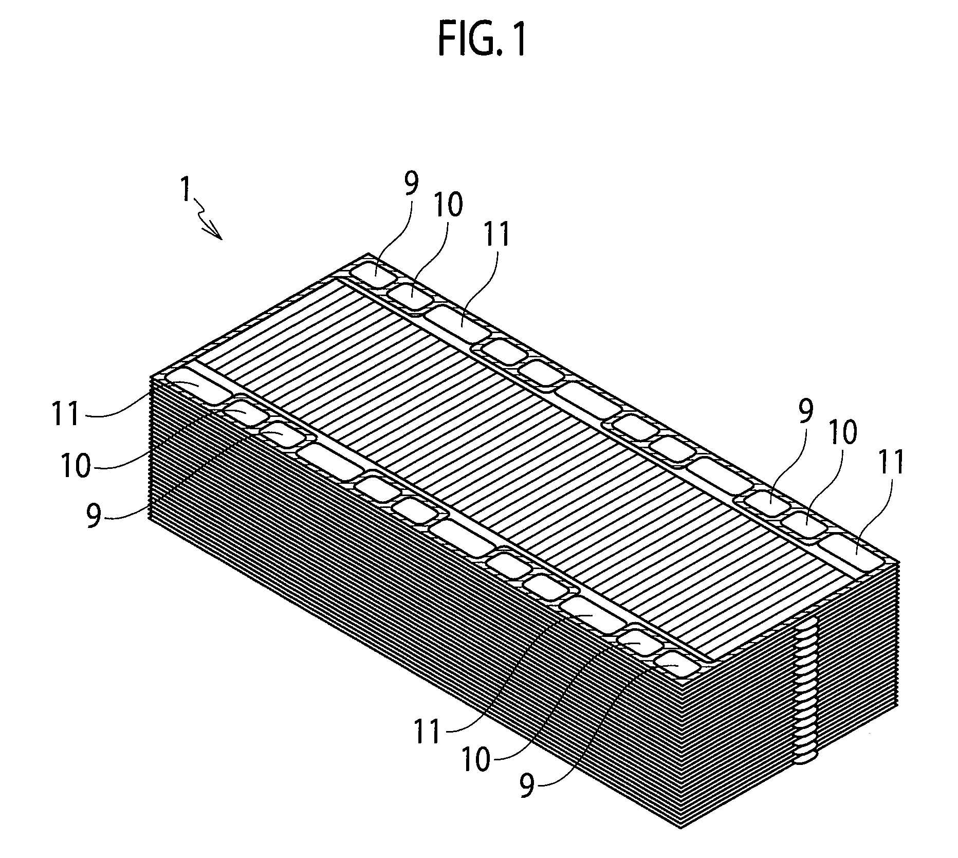
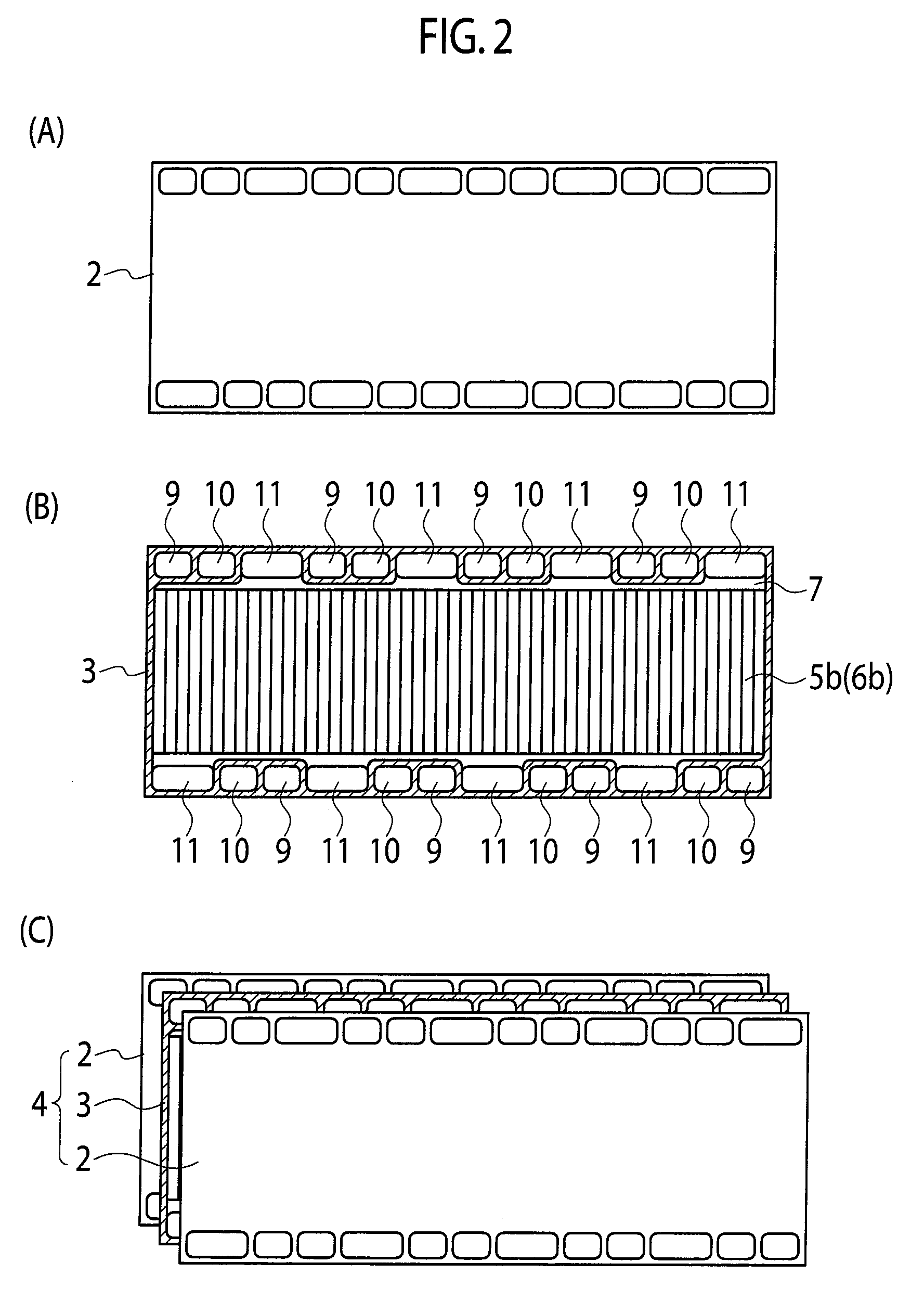
A fuel cell (1) of the present invention includes a stacked body of a membrane electrode assembly (3) including anode and cathode electrode layers on both surfaces of an electrolyte membrane (7) and of separators (2). Then, the membrane electrode assembly (3) and the separators (2) are formed into a substantially rectangular shape, the separators (2) are smooth or include flow passages, and each of the electrode layers includes a gas diffusion layer and a catalyst layer. Moreover, an aspect ratio R as a ratio (flow passage length/flow passage width) of a flow passage length with respect to a flow passage width on a cathode side or anode side of the membrane electrode assembly (3) is 0.01 or more to less than 2. Furthermore, a horizontal direction equivalent diameter D (mm) of the gas diffusion layer or the flow passages satisfies Expression (1):
D=B×(R×Acat)1/3  Expression (1)
(where Acat is a catalyst area (cm2) of the membrane electrode assembly (3), and B is a constant of 0.005 or more to 0.2 or less).

Description

TECHNICAL FIELD[0001]The present invention relates to a fuel cell and to a vehicle including the fuel cell. In detail, the present invention relates to a fuel cell that is miniaturized while maintaining anti-flooding characteristics thereof, and to a vehicle including the fuel cell.BACKGROUND ART[0002]A fuel cell is a kind of a power generation device that takes out electrical energy by electrochemically oxidizing fuel such as hydrogen and methanol, and in recent years, has attracted attention as a supply source of clean energy. The fuel cell is classified into a phosphoric acid type, a molten carbonate type, a solid oxide type, a polymer electrolyte type and the like in accordance with types of electrolytes for use.[0003]Among them, the polymer electrolyte fuel cell (PEFC) includes a membrane electrode assembly (MEA) in which electrodes are arranged on both surfaces of an electrolyte membrane. Then, the PEFC generates electricity by supplying hydrogen (fuel gas) to one surface of t...

Claims


Application Information

Patent Timeline
Patent Type & Authority Applications(United States)
IPC IPC(8): H01M8/10
CPCH01M8/026H01M8/1004H01M2008/1095H01M8/241Y02E60/521Y02T90/32H01M2250/20Y02E60/50Y02T90/40H01M8/2483H01M8/0267H01M8/242
Inventor HASEGAWA, TAKUYAFUJIEDA, RYUJI
Owner NISSAN MOTOR CO LTD
Why Eureka
Try Eureka