Measuring Brake Wear

a technology of brake wear and measurement, applied in the direction of brake systems, process and machine control, instruments, etc., can solve the problems of affecting the design of the machine, and affecting the operation of the machin

Active Publication Date: 2012-08-30
DEERE & CO
View PDF0 Cites 23 Cited by
  • Summary
  • Abstract
  • Description
  • Claims
  • Application Information

AI Technical Summary

Benefits of technology

[0011]Thus, it will be appreciated that the ability of the electric controller to easily derive a break-free torque value from the command signal being sent to the motor at the time slippage occurs in the disc pack makes it possible to determine the break-free torque without requiring any other measuring device.

Problems solved by technology

The issue, especially in wet brakes used in construction equipment having final drives embodying speed reduction gearing, is that checking the amount of wear visually or mechanically is difficult due to the brakes being housed at a location inboard of the final drive gears, wheel drive hub and spindle or axle.
Tests to determine the reliability of parking brakes are becoming routine but have the drawback that most are pass / fail type tests with a failure requiring that the machine be shut down until the condition giving rise to the failure is remedied.
This wear measurement arrangement has the disadvantage that the brake piston for effecting engagement of the brake disc pack must be located so as to be accessible for permitting its movement to be manually measured, thus placing design constraints on where a park and service brake assembly may be placed when used with a final drive arrangement.
This wear measurement has the further disadvantage of requiring the operator to dismount the cab and manually perform measurements, which is time-consuming.
This manner of checking brake integrity has the drawback of requiring a sensor arrangement for determining the relative rotation between the brake-applying member and the reaction plate, which adds additional cost to the final drive arrangement.

Method used


Image

  • Measuring Brake Wear
  • Measuring Brake Wear
  • Measuring Brake Wear

Examples


Embodiment Construction

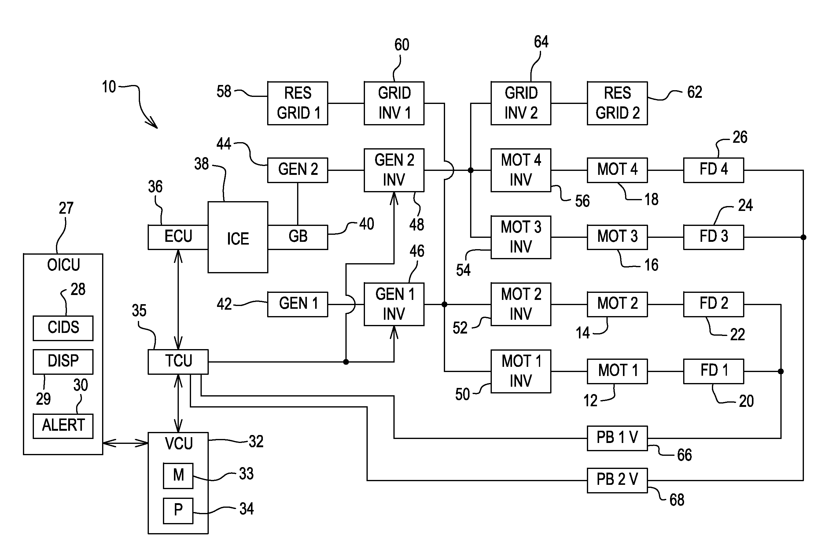
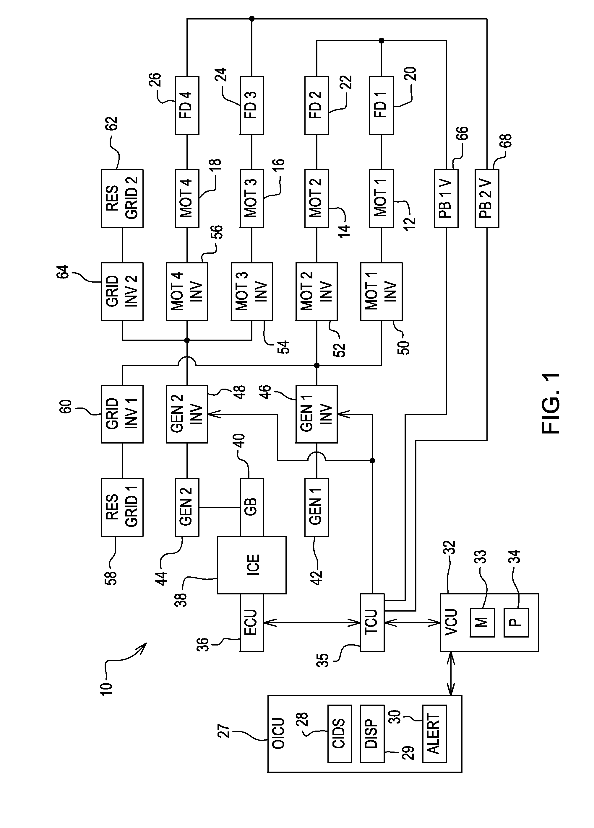
[0017]Referring now to FIG. 1, there is shown a motor control system 10 for controlling four identical wheel drive Motors (MOT 1) 12, (MOT 2) 14, (MOT 3) 16 and (MOT 4) 18 having output shafts coupled for respectively delivering torque for driving four identical Final Drives (FD 1) 20, (FD 2) 22, (FD 3) 24 and FD 4) 26 for driving front and rear pairs of drive wheels (not shown) of an industrial vehicle such as a loader, for example. The electric Motors 12, 14, 16 and 18 are preferably 3-phase switched reluctance motors, but need not be.

[0018]The motor control system 10 includes an Operator Interface Control Unit (OICU) 27 including Control Input Devices (CIDS) 28 such as throttle and brake test input buttons, for example, by which an operator may send out various control signals. The OICU 27 also includes a Display (DISP) 29 and an Alert Device (AD) 30, the latter being an audio or visual alert device such as a buzzer or light, for example, by which an operator is alerted to certai...


PUM


Abstract

A final drive assembly is driven by an electric motor and includes a park and service brake arrangement including a shared disc brake pack that is compressed by a preload exerted by a compression spring arrangement defined by a stack of Belleville springs for establishing an engaged park brake condition in the absence of pressurized brake actuating fluid being routed to a park brake piston. An electrical control is provided for computing disc brake pack wear based on a stored load curve of the stack of Belleville springs containing information correlating preload amounts to various compressed heights of the stack of Belleville springs, and on the magnitude of a drive signal sent to the electric motor for causing sufficient drive torque to be developed for causing the rotor discs of the engaged disc brake pack to slip relative to the stator discs.

Description

FIELD OF THE INVENTION[0001]The present invention relates to vehicle service and park brakes, and, more particularly, relates to devices for indicating brake wear of a brake disc pack of a service and park brake assembly embodied in a final drive assembly including an input drive shaft driven by an electric motor.BACKGROUND OF THE INVENTION[0002]Routine service on many types of machines and vehicles involves checking the status of the brakes, in particular, the wear of brake pads or disks forming part of the brakes. Much effort has been made by designers to arrive at a good method for measuring brake wear. Additionally, there are regulations in some areas that mandate regular capacity checks on park brakes.[0003]The issue, especially in wet brakes used in construction equipment having final drives embodying speed reduction gearing, is that checking the amount of wear visually or mechanically is difficult due to the brakes being housed at a location inboard of the final drive gears, ...

Claims


Application Information

Patent Timeline
Patent Type & Authority Applications(United States)
IPC IPC(8): G06F19/00B60T8/17B60L50/16
CPCB60T1/062B60T17/221B60T13/22B60T1/065
Inventor PFOHL, KEVIN L.ANDERSON, ERIC R.BESLER, MARK J.
Owner DEERE & CO
Why Eureka
Try Eureka