Displacement detection mechanism and scanning probe mircoscope using the same

a technology of displacement detection and scanning probe, which is applied in the direction of instruments, measurement devices, nanotechnology, etc., can solve the problems of difficult irradiation of samples with light, inability to accurately measure physical property information, and affecting the accuracy of physical property measurement, so as to facilitate the electrical property measurement

Inactive Publication Date: 2012-09-06
HITACHI HIGH TECH SCI CORP
View PDF3 Cites 5 Cited by
  • Summary
  • Abstract
  • Description
  • Claims
  • Application Information

AI Technical Summary

Benefits of technology

[0011]According to the present invention, there is provided a displacement detection mechanism for a cantilever, for detecting a displacement of a cantilever that generates a certain vibration in a direction opposed to a reference table to be a reference of a position, the displacement detection mechanism including capacitance change detection means that detects a change of capacitance between the cantilever and the reference table due to a change of vibration of the cantilever, in which the displacement of the cantilever is evaluated based on the change of capacitance. With this structure, a defect of the optical cantilever method or the self-detection method can be eliminated.
[0016]According to the scanning probe microscope of the present invention, it is possible to detect a displacement of the cantilever as a change of capacitance between a lever portion of the cantilever and the sample.
[0018]In addition, it is not necessary for the cantilever to be equipped with a piezoresistance sensor in the self-detection type, and hence a general purpose cantilever available in the market (including a conductive cantilever) can be used. Further, even if the cantilever is in an electric field, the cantilever is not affected by the electric field because the cantilever has no piezoresistance sensor. Therefore, it is possible to easily perform the electrical property measurement with the KFM or the EFM.

Problems solved by technology

However, because light is applied to the sample too, the physical property measurement may be affected by the light.
In particular, when a potential or current of the sample surface is measured, the sample itself may change its physical property value by photoexcitation or the like so that accurate physical property information cannot be measured.
In addition, for the same reason, it may be difficult to irradiate the sample with light so as to measure a change of physical property information of the sample between presence and absence of the light.
On the other hand, the method of using the piezoresistance type self-detecting cantilever does not use light for measuring a displacement of the cantilever, and hence the method does not have the above-mentioned influence.
However, there are various restrictions when the electrical property is measured with the KFM or the like.
As a matter of course, a usual cantilever available in the market cannot be used.
In addition, in the electrical property measurement, a conductive cantilever having a metal coated probe is usually used, but the piezoresistance type self-detecting cantilever having a metal coated probe requires a more complicated structure and manufacturing process, and hence there is difficulty in manufacturing the cantilever itself.
As a result, the displacement current generated in the piezoresistor may be mixed into a displacement signal of the lever as noise, and hence accurate measurement cannot be performed.
Concerning this point, there is reported a measurement example of the KFM utilizing a phase difference between an alternating electric field affecting the piezoresistance sensor and an alternating electric field affecting between the probe and the sample, but a structure of the apparatus is complicated, and the resolution is low (see M.Takahashi, T. Igarashi, T. Ujihara and T. Takahashi: “Photovoltage Mapping on Polycrystalline Silicon Solar Cells by Kelvin Prove Force Microscopy with Piezoresistive Cantilever”, Jpn. J. Appl. Phys., 46, 548 (2007)).

Method used


Image

  • Displacement detection mechanism and scanning probe mircoscope using the same
  • Displacement detection mechanism and scanning probe mircoscope using the same
  • Displacement detection mechanism and scanning probe mircoscope using the same

Examples


first embodiment

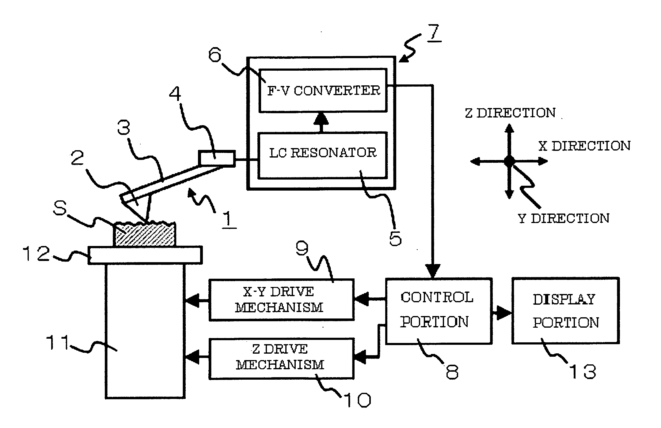
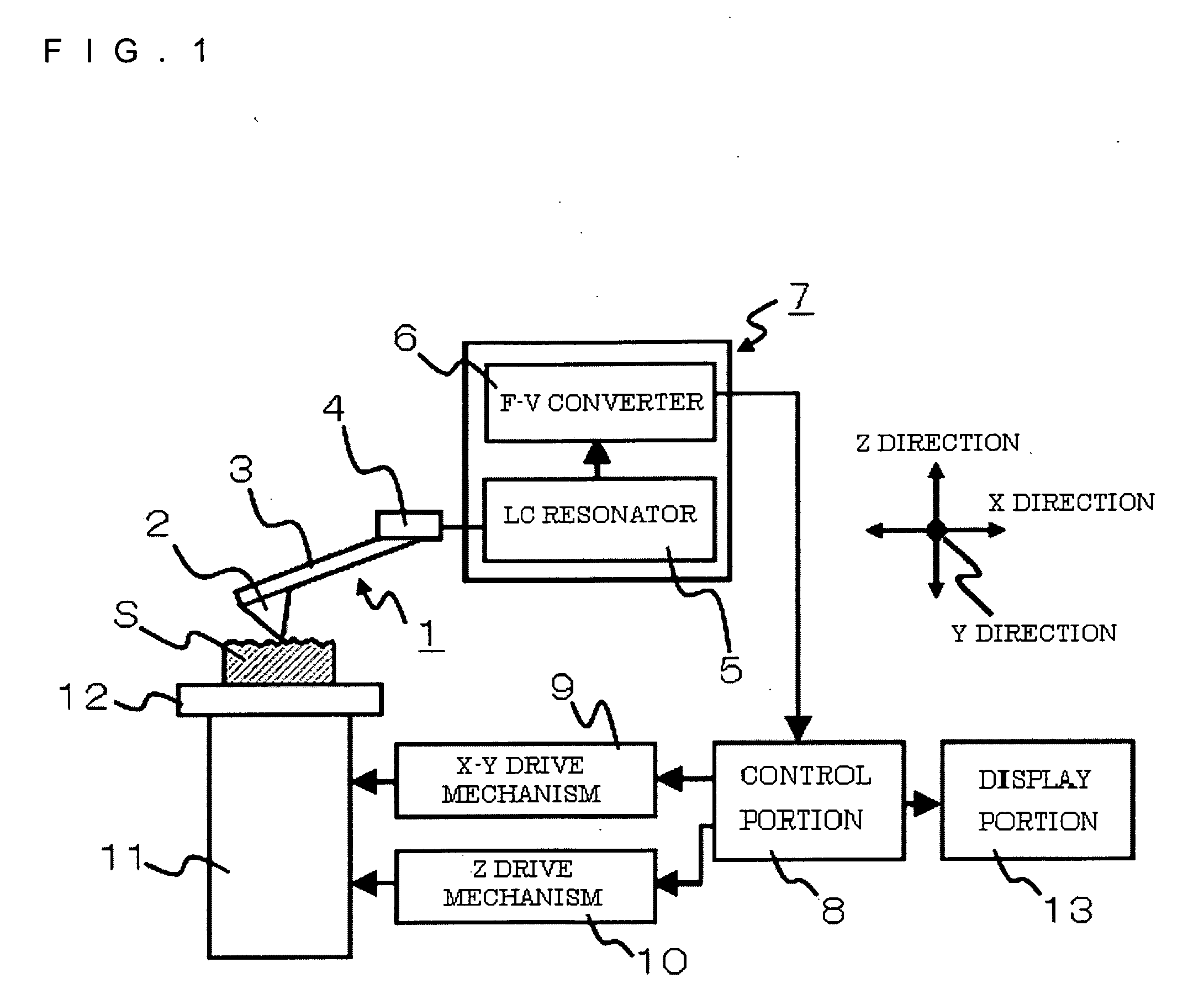
[0025]FIG. 1 illustrates an example of a structure of the scanning probe microscope according to the present invention.

[0026]The scanning probe microscope of the present invention includes a cantilever 1 that has a probe 2 whose tip is disposed to be opposed to a sample surface S of a sample placed on a sample table 12 and can perform scanning relatively to the sample surface S in X and Y directions parallel to the sample surface S and move in a Z direction perpendicular to the sample surface S, cantilever vibrator means 4 that can vibrate the cantilever 1, and a cantilever displacement detection portion 7 that detects a displacement of the cantilever 1. The sample table 12 or the sample S placed thereon is a reference of a position of the cantilever 1, and a capacitance between the cantilever 1 and a surface of the sample S or the sample table 12 is important.

[0027]The sample table 12 is attached to a three-dimensional actuator 11, and can move the probe 2 and the sample surface S ...

second embodiment

[0038]FIG. 3 illustrates an example of a structure of a scanning probe microscope according to the present invention.

[0039]The sample table 12 is connected to a signal generator 15 for applying an alternating electric field between the probe and the sample. In addition, the displacement information of the cantilever detected by the cantilever displacement detection portion 7 is sent to a lock-in amplifier 14 so that an amplitude and phase of the same frequency component as that of the signal generator 15 or twice or more of the frequency component of the signal generator 15 can be detected in a synchronous manner. The amplitude and the phase component detected here are the vibration amplitude and the phase component of the cantilever due to an electrostatic force between the probe and the sample caused by the alternating electric field, and these signals are information obtained by the EFM measurement. In addition, the KFM measurement can be performed by applying a DC bias to the sa...

third embodiment

[0040]FIG. 4 illustrates an example of a structure of a scanning probe microscope according to the present invention.

[0041]The microscope includes a physical property illumination device 17 so that the sample and / or the probe are irradiated with light L. With this structure, the EFM measurement or the KFM measurement is performed in a state without illumination of the light L, and after that, the EFM measurement or the KFM measurement is performed in a state with illumination of the light L. Thus, it is possible to obtain shape information or physical property information of the sample surface between presence and absence of the light. In addition, by changing intensity of the light L by the illumination device 17, it is possible to observe a difference of results of the KFM measurement or the EFM measurement due to the intensity or a difference thereof. With this structure, light intensity dependence of the shape information or the physical property information of the sample surfac...


PUM


Abstract

Provided are a displacement detection mechanism for a cantilever which does not use an optical cantilever method or self-detection type displacement detection, and a scanning probe microscope using the same. A cantilever displacement detector constituted of an LC resonator and an F-V converter detects a change of capacitance between a cantilever and a sample surface so that a displacement of the cantilever can be detected. Thus, shape measurement and physical property measurement can be performed in a state in which light is blocked. Further, a change of a sample shape and physical property information can be measured between presence and absence of the light.

Description

BACKGROUND OF THE INVENTION[0001]1. Field of the Invention[0002]The present invention relates to a displacement measuring method for measuring a displacement of a cantilever accurately, and more particularly, to a scanning probe microscope that can observe, by using the method, a surface shape or physical property information of a sample by scanning a surface of the sample with a probe.[0003]2. Description of the Related Art[0004]The scanning probe microscope (hereinafter, referred to as SPM) is a microscope for measuring a surface shape or physical property information of a sample, and there are proposed various measuring modes of the SPM. For instance, there are a scanning tunneling microscope (hereinafter, referred to as an STM) that maintains a tunnel current flowing between the probe and the sample to be constant so as to obtain the surface shape, and an atomic force microscope (hereinafter, referred to as AFM) that detects an atomic force between the probe and the sample so as...

Claims


Application Information

Patent Timeline
Patent Type & Authority Applications(United States)
IPC IPC(8): G01Q10/00G01Q20/00
CPCB82Y35/00G01Q60/30G01Q20/00
Inventor HIROSE, RYUSUKE
Owner HITACHI HIGH TECH SCI CORP
Why Eureka
Try Eureka