Airfoil and corresponding guide vane, blade, gas turbine and turbomachine

Inactive Publication Date: 2012-09-13
SIEMENS AG
View PDF8 Cites 26 Cited by
  • Summary
  • Abstract
  • Description
  • Claims
  • Application Information

AI Technical Summary

Benefits of technology

[0012]The present invention seeks to mitigate drawbacks of the prior art. Specifically it is an object of the invention to provide an airfoil or a compo

Problems solved by technology

Hardly any air should be able to leave the path of the air because this would lead to an

Method used


Image

  • Airfoil and corresponding guide vane, blade, gas turbine and turbomachine
  • Airfoil and corresponding guide vane, blade, gas turbine and turbomachine
  • Airfoil and corresponding guide vane, blade, gas turbine and turbomachine

Examples


first embodiment

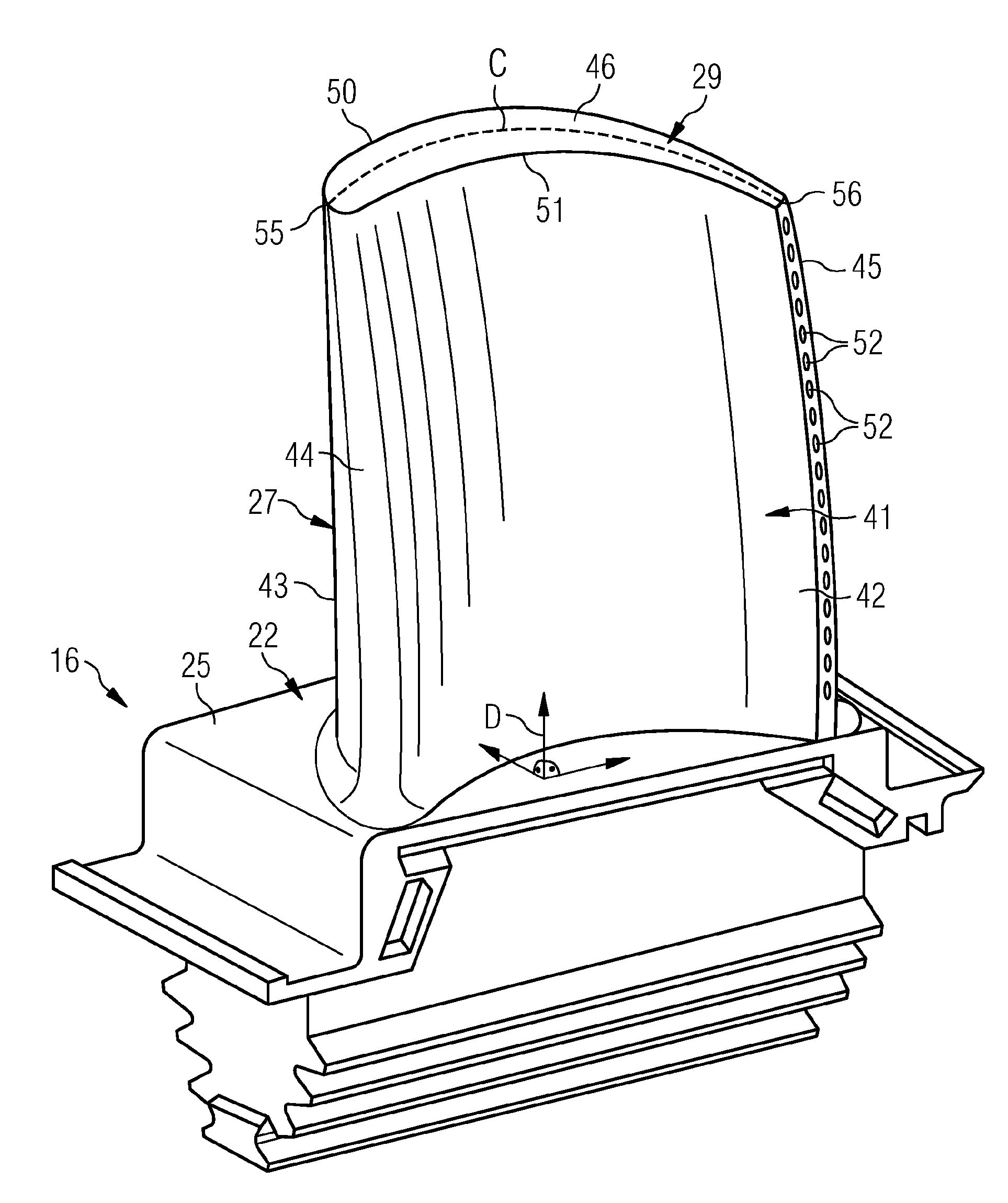
[0069]FIG. 4A specifies a first embodiment, in which the ribs extend in parallel between the leading tip edge 55 and the trailing tip edge 56. The ribs, defined by alternating first surfaces 70 and second surfaces 71, may be completely straight, or may follow the curved form of the airfoil along the pressure surface 42 and / or the suction surface 43. Alternatively the ribs may be arranged perpendicular to the direction of rotation of the airfoil 27 or may be arranged at a specific angle in respect of the direction of rotation.

second embodiment

[0070]In a second embodiment according to FIG. 4B, again parallel ribs of alternating first surfaces 70 and second surfaces 71 are shown. The direction of the ribs is substantially perpendicular to at least one area of the suction surface 43 and / or pressure surface 42. In FIG. 4B each partial surface of the first surface 70 is substantially rectangular. Alternatively first surfaces 70 may be in form of a trapezium if the grooves between the ribs are not perfectly parallel.

[0071]Not shown in the figures, the embodiments of FIG. 4A and FIG. 4B may be combined to gain a grid pattern with a set of parallel grooves extending between the leading tip edge 55 and the trailing tip edge 56 and a set of parallel grooves extending between the suction surface 43 and the pressure surface 42.

[0072]Further variants of grid patterns are shown in FIGS. 4C and 4D. In both variants a first plurality of ribs or grooves are arranged diagonally in direction of the trailing tip edge 56 of the airfoil 27 an...


PUM


Abstract

An airfoil suitable for being arranged in a compressor section of the gas turbine includes a platform, a pressure surface and a suction surface, and a tip region. The tip region is located between the pressure and the suction surface opposite to the platform in respect of the pressure and the suction surfaces, being a distant end of the airfoil in direction along the first direction perpendicular to the platform. The tip region includes a first surface with a first distance to the platform along the first direction, and a second surface with a second distance to the platform along the first direction. The first distance is greater than the second distance and the first surface and the second surface together build a profiled surface. The profiled surface is a ribbed surface. The material of the first surface is deformable to bend away from the rotation direction of the airfoil.

Description

FIELD OF THE INVENTION[0001]The invention relates to an airfoil, a guide vane, and a blade, particularly of a compressor or a turbine section of a turbomachine. Furthermore the invention relates to a turbomachine, especially a gas turbine, comprising at least one airfoil.BACKGROUND OF THE INVENTION[0002]A conventional gas turbine engine comprises a compressor which is used for pressurising ambient air. The compressed air is mixed with fuel and burned in a combustor. Energy is extracted from the hot combustion gas by passing it through a turbine section of the gas turbine engine. The rotatable sections of an engine typically comprise annular arrays of compressor or turbine rotor blades, the blades normally being intersected with annular arrays of static aerodynamic guide vanes, also called stator vanes. Each disc of guide vanes and each disc of rotor blades are arranged axially alternately. One disc of rotor blades and one disc of guide vanes are referred to as a stage. The guide van...

Claims


Application Information

Patent Timeline
IPC IPC(8): F01D5/20F01D1/04
CPCF01D5/20F16J15/4472F16J15/44F01D11/127
Inventor SHEPHERD, ANDREWTWELL, PHILIP
Owner SIEMENS AG
Why Eureka
Try Eureka