
Elastic high voltage electric phases for hyper depth power umbilical's

a technology of electric phases and umbilicals, applied in the manufacture of cables/conductors, electrical equipment, conductors, etc., can solve the problems of considerable mechanical stress of the current power umbilical cable, for example used, and withstanding approximately 0 , to achieve the effect of less material in its manufactur

Inactive Publication Date: 2012-09-20
NEXANS
View PDF14 Cites 39 Cited by
  • Summary
  • Abstract
  • Description
  • Claims
  • Application Information

AI Technical Summary

Benefits of technology

[0009]Moreover, the present invention seeks to enhance a power carrying capacity of power umbilical cables for a given weight and quantity of material employed in producing the umbilical cable.
[0010]Furthermore, the present invention seeks to provide an umbilical cable which can be employed to greater depths in offshore environments in comparison to conventional power umbilical cables.
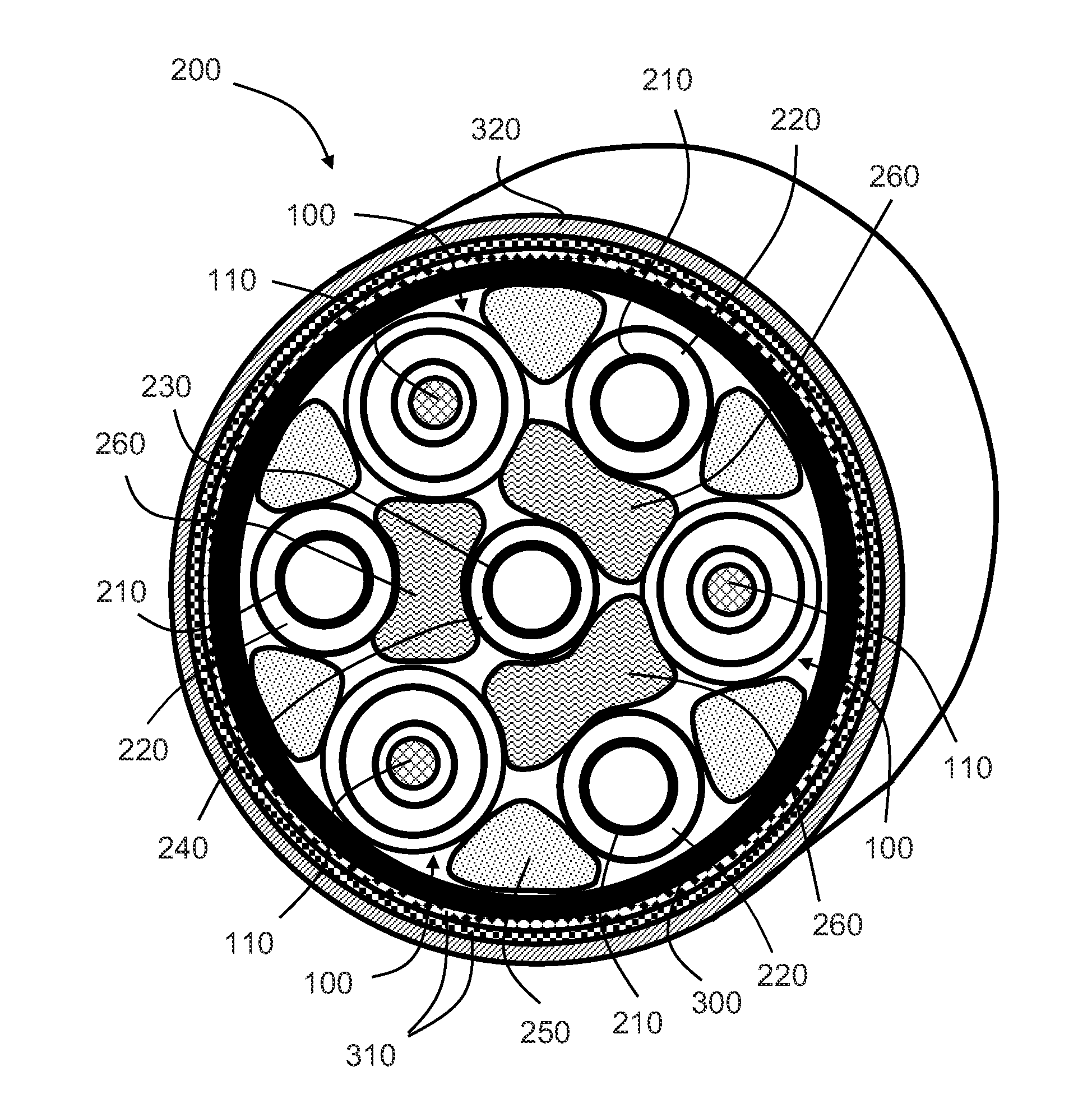
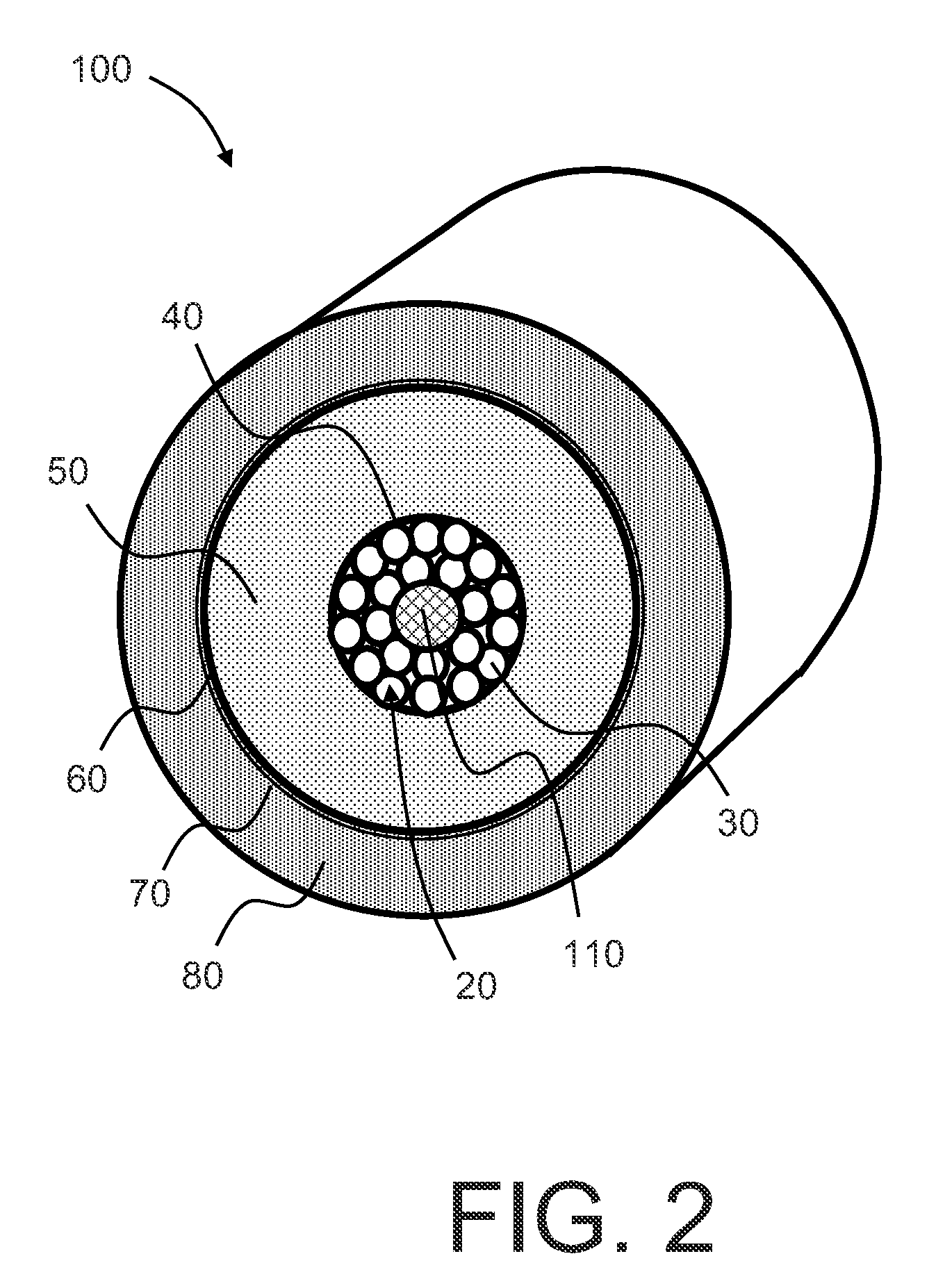
[0012]each current conducting core includes at a central portion therein and surrounded by the plurality of conductive metal wires, a flexible element to enable the wires to move in a radial direction to reduce their strain when the umbilical cable is subject in operation to stress causing the one or more elongate structural components to be axially strained.
[0013]The invention is of advantage in that inclusion of the flexible elements within the cores enables the cable to operate to a strain limit determined by the elongate structure components.
[0021]According to a second aspect of the present invention, there is provided a phase including a core including a plurality of elongate conductive wires, the core being surrounded by a circumferential insulating sheath, characterized in that the core includes a central elongate element therein surrounded by the plurality of wires, the central elongate element being operable to flex to reduce a strain experienced in operation by the plurality of elongate conductive wires.
[0023]According to a third aspect of the invention, there is provided a method of enhancing strain properties of a power umbilical cable, characterized in that the method includes:(a) arranging for a power umbilical cable to including one or more axial elongate phases for conducting electrical current, and one or more axial elongate structural components adapted to undergo stress to withstand axial and bending strain applied to the power umbilical cable in operation, the umbilical cable being protected within an outer protection layer; and(b) including in the one or more elongate phases corresponding one or more current conducting cores, wherein each core comprises a plurality of mutually abutting conductive metal wires, and wherein each current conducting core includes at a central portion therein surrounded by the plurality of conductive metal wires, the central portion including a flexible element operable to enable the wires to move in a radial direction to reduce their strain when the umbilical cable is subject in operation to stress causing the one or more elongate structural components to be axially strained.

Problems solved by technology

Contemporary power umbilical cables, for example used in offshore environments such as laid onto a seabed, are subject to considerable mechanical stress when being installed and also subsequently when in operation.
A problem arising in practice is that the strengthening steel tubes are capable of withstanding a strain of approximately 0.3% in response to stress being applied, whereas the copper phases are only capable of withstanding approximately 0.1% strain.
Excessive elongation of the copper phases causes the phases to break.
In consequence, the umbilical cable is correspondingly heavier and more costly than necessary in respect of the steel strengthening tubes.
Consequently, it is it is difficult to obtain elongation due to radial deformation caused by axial force, because the strengthening tubes and the power phases will undergo a mutually similar elongation when subjected, for example, to axial stress.
Such a length is impractically short for future offshore installations.

Method used


Image

  • Elastic high voltage electric phases for hyper depth power umbilical's
  • Elastic high voltage electric phases for hyper depth power umbilical's
  • Elastic high voltage electric phases for hyper depth power umbilical's

Examples


Embodiment Construction

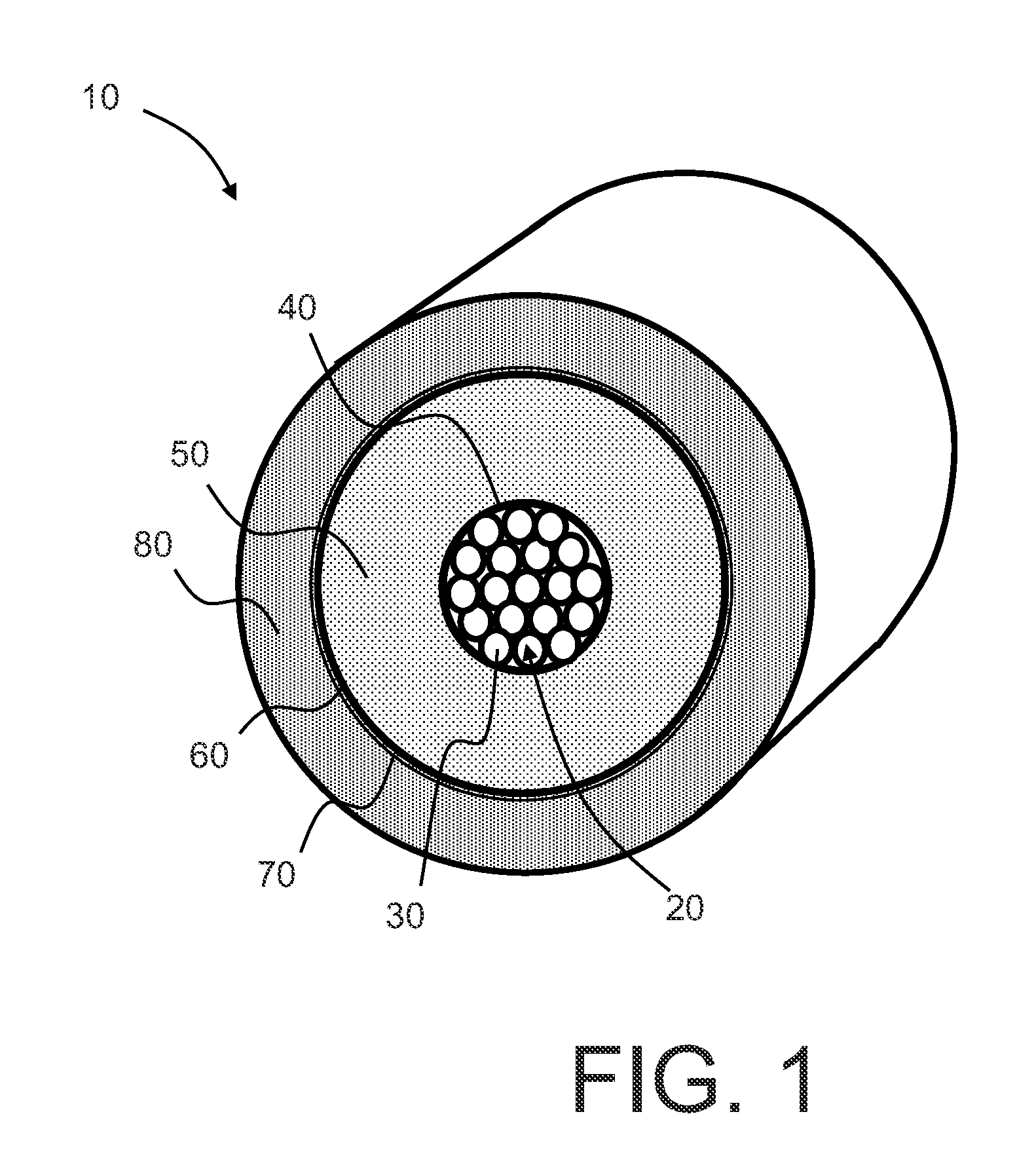
[0031]In FIG. 1, a conventional copper phase of a power umbilical cable is indicated generally by 10. The copper phase 10 includes a core 20 comprising a plurality of annealed Copper wires 30; optionally, wires fabricated from other materials are employed, for example Aluminium. A semi-conducting sheath 40 circumferentially surrounds the core 20. Moreover, a cross-linked polyethylene polymer insulation layer 50 circumferentially surrounds the sheath 40. Furthermore, a semi-conducting sheath 60 circumferentially surrounds the polymer insulation layer 50. Additionally, a copper wrapping 70 and finally a cross-linked polyethylene polymer insulation layer 80 circumferentially surrounds the semi-conducting sheath 60. The semi-conductor layers 40, 60 serve to reduce a risk of localized electric field concentrations at an inner and outer periphery of the layer 50 which could risk electrical discharge from the core 20 to the copper wrapping 70.

[0032]The present invention is concerned with c...


PUM

PropertyMeasurementUnit
Diameteraaaaaaaaaa
Flexibilityaaaaaaaaaa
Electrical conductoraaaaaaaaaa

Abstract

A power umbilical cable includes one or more axial elongate phases for conducting electrical current, and one or more axial elongate structural components adapted to undergo stress to withstand axial and bending strain applied to the power umbilical cable in operation. The umbilical cable has an outer protection layer, each of the phases having a conductive core made of a plurality of metal wires. Each current conducting core includes at a central portion therein, and surrounded by the plurality of conductive metal wires, a flexible element to enable the wires to move in a radial direction to reduce their strain when the umbilical cable is subject in operation to stress causing the one or more elongate structural components to be axially strained.

Description

RELATED APPLICATION[0001]This application claims the benefit of priority to Norwegian Patent Application No. 2011 110393, filed on Mar. 14, 2011, the entirety of which is incorporated by reference.BACKGROUND[0002]1. Field of the Invention[0003]The present invention relates to power umbilical cables, for example to hyper depth power umbilical cables including elastic high voltage electrical phases. Moreover, the present invention relates to elastic high voltage electrical phases suitable for use in constructing such umbilical cables.[0004]2. Description of the Related Art[0005]Contemporary power umbilical cables, for example used in offshore environments such as laid onto a seabed, are subject to considerable mechanical stress when being installed and also subsequently when in operation. It is conventional practice to employ insulated multi-stranded copper conductors enclosed within a sealing polymer outer sheath for carrying electric current through these power umbilical cables. The...

Claims


Application Information

Patent Timeline
IPC IPC(8): H01B7/18H01B13/00
CPCH01B7/045Y10T29/49117H01B7/182
Inventor LUND, SJUR KRISTIAN
Owner NEXANS
Learn More