Mass analyzer apparatus and systems operative for focusing ribbon ion beams and for separating desired ion species from unwanted ion species in ribbon ion beams

Inactive Publication Date: 2012-09-20
WHITE NICHOLAS R
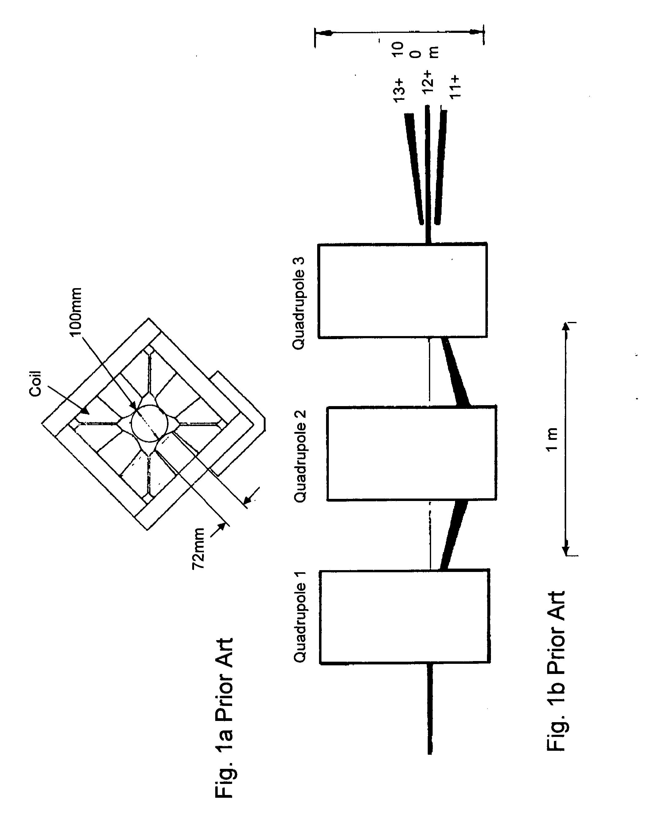
View PDF5 Cites 5 Cited by
  • Summary
  • Abstract
  • Description
  • Claims
  • Application Information

AI Technical Summary

Benefits of technology

[0029]Consequently in today's technology, it is highly desirable to find an effective means for separating a variety of unwanted ion species from a traveling ribbon-shaped ion beam in which the size of the travel passage for the beam in its major dimension can be extended to an arbitrary degree; and where there is no need

Problems solved by technology

Otherwise, as the device is extended in this length dimension, the number of ampere turns required to generate the required field increases, there is a tendency for flux leakage to flow from the device, and the size and weight of the device grow inconveniently large.
The occurrence of either or both of these events is undesirable; nevertheless, these disadvantageous factors continue to appear repeatedly and must be routinely compensated for—owing to the fact that it is today conventional to use such a dimension-extended magnetic field for mass separation.
On the other hand, a magnetic field lying in a plane in which the ion travel trajectories are moving does not directly introduce any useful deflection or dispersion in that plane.
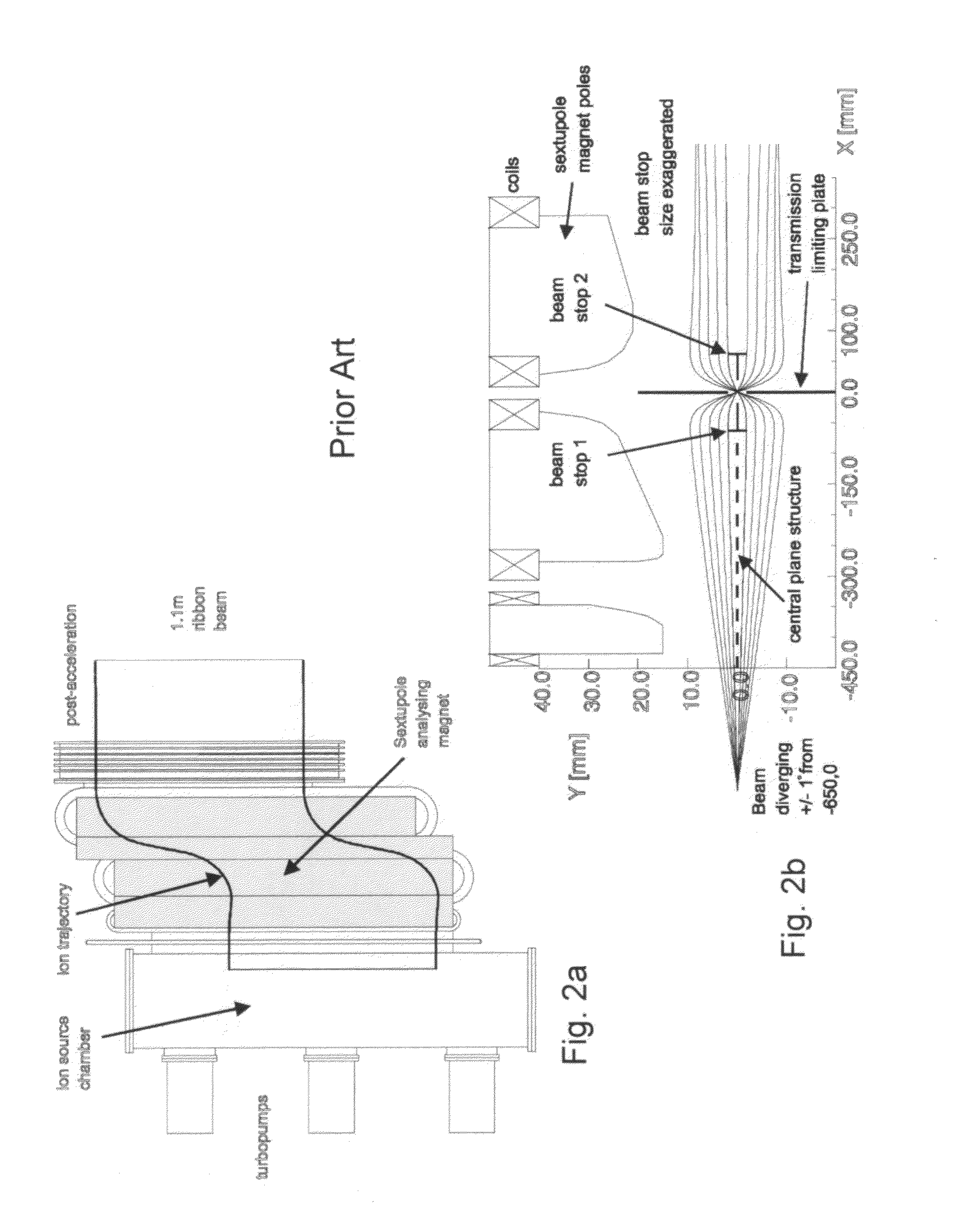
The shearing in the IBIS 1000 ion implanter was found to be significant but tolerable, given that the ion beam in question was used at energies above about 50 keV, but at lower energies it would have had adverse effects.
In 1990-1991 technology terms, this potential capability was deemed to not be worth the added complication for the ribbon-shaped ion beam application.
Thus, the Satoh apparatus cannot and does not fulfill the present need.
Other magnetic devices used within the Chen & White apparatus (based upon U.S. Pat. Nos. 7,105,839; 7,078,713; and 8,035,087 for focusing and controlling uniformity and direction of the ion beams), can be scaled upwards for larger sized ion beams because their magnetic fields are not aligned with the beam's major transverse direction—but they are not capable of separating beams of different mass, nor of providing a scalable one-dimensional focusing ability in a direction transverse to a ribbon ion beam without providing an overwhelming unwanted defocusing effect along the major dimension.
This was not their intended usage, and is beyond their structural and functional capabilities.
On this factual basis, and especially because the Aitken device operates on the verge of completel

Method used


Image

  • Mass analyzer apparatus and systems operative for focusing ribbon ion beams and for separating desired ion species from unwanted ion species in ribbon ion beams
  • Mass analyzer apparatus and systems operative for focusing ribbon ion beams and for separating desired ion species from unwanted ion species in ribbon ion beams
  • Mass analyzer apparatus and systems operative for focusing ribbon ion beams and for separating desired ion species from unwanted ion species in ribbon ion beams

Examples


second embodiment

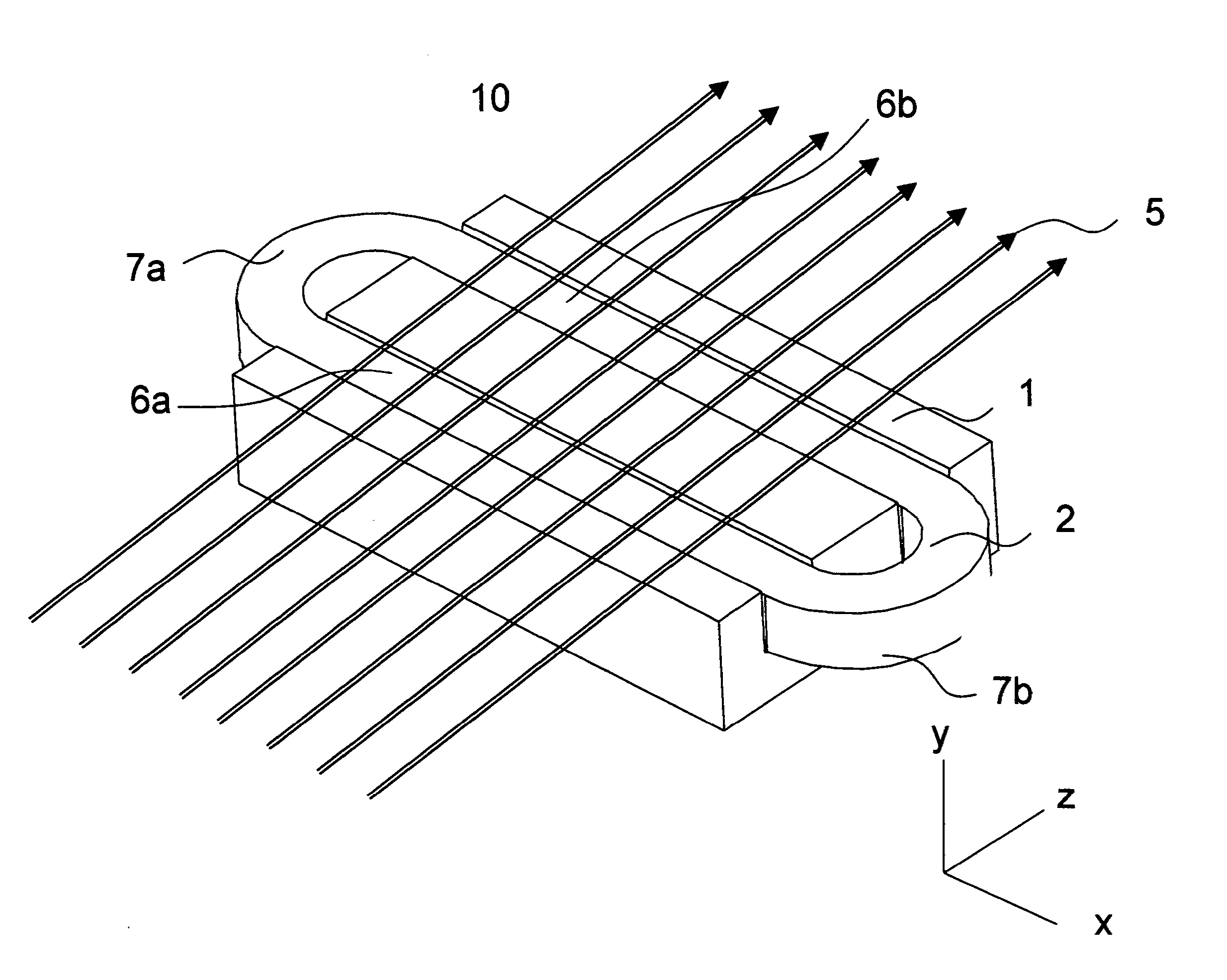
[0102]an operational assembly which utilizes the basic apparatus described above in combination with a flat ferromagnetic plate 3 is shown by FIG. 4a. The ferromagnetic plate 3 lies in and similarly defines a z-x plane at coordinate y=0.

[0103]In this embodiment, there is a fixed gap distance of predetermined size separating the exposed face of the flat ferromagnetic plate 3 from the exposed face of the E-block-coil combination which is located at a coordinate of y=y1; and the traveling charged particle beam transversely passes over the length of this fixed gap distance and through the extended magnetic field present therein.

[0104]The extended magnetic field (generated by the E-block-coil combination) is effectively terminated on this ferromagnetic plate 3 at right angles to its internal exposed surface or face. In the plane y=0, there are essentially no magnetic field components in the x- or z-direction. However, at non-zero y coordinates, these components will appear.

[0105]As befor...

fourth embodiment

[0115]the invention is very much like that of Apparatus Version 3 as described above—except that the current in one of the coils is reversed, and thus the individual currents in the two discrete coils are opposed in charge / polarity. In this Apparatus Version 4, therefore, the most notable feature is that the two discrete E-block-coil combinations are oppositely magnetized and repel each other.

[0116]In evidence of this feature, FIG. 6 plots the field lines in this geometry; and the external fields are minimized in this geometry. This configuration is preferred for both performance and ease of analysis; as well as for the straight lengths of conductor which are arranged so that, in cross section, they are centered on the apexes of a rectangle. The direction of current alternates as one moves around the rectangle as shown in FIG. 9b, in contrast to the different current flow shown in FIG. 9a.

[0117]There is also a difference in the origin of the y-focusing in this arrangement. In Appar...

fifth embodiment

[0120]the apparatus optionally omits the coils from the construct and replaces part of the steel or other ferromagnetic material in the E-block mounting with a permanent magnet. However, such a change in structure means that the magnetic rigidity selected by the device can no longer be quickly adjusted. Adjustment of the traveling beam must now be made by changing the spacing of the components over a narrow range.

[0121]This alternative version works best with the field orientation as described above for Apparatus Version 4. That of Apparatus Version 3 is also possible, but net y deflection is difficult to control without additional coils 22; and adding such coils negates the benefit of permanent magnets. Also, for large sized beams, the cost of electricity to power the coils may be very significant—so if an application requiring a single beam species exists, the permanent magnet version may be markedly more advantageous.

Apparatus Version 6


PUM


Abstract

The present invention is an apparatus and multi-unit assembly which is able to achieve two different and highly desirable functions: A focusing of a charged particle beam; and a mass separation of desired ion species from unwanted ion species in traveling ion beams. The apparatus is a simply organized and easily manufactured article; is relatively light-weight and less expensive to make; and is easier to install, align, and operate than conventionally available devices.

Description

PRIORITY CLAIM[0001]This invention was first filed on Mar. 17, 2011 as U.S. Provisional Patent Application Ser. No. 61 / 465,303. The priority date and legal benefits of this first filing are expressly claimed hereby.FIELD OF THE INVENTION[0002]The present invention concerns magnetic lenses which are applied to ribbon-shaped ion beams in ion implantation apparatus and systems for the purpose of selecting desired ions by mass, as well as for focusing. In such systems, the ribbon-shaped ion beams and the lenses would ideally have planar symmetry, with a constant cross section in the width dimension, over a distance many times greater than the narrow beam dimension.BACKGROUND OF THE INVENTIONUnderlying Facts and Historical Considerations[0003]The use of magnetic lens for focusing purposes is conventional and long known; and the use of offset magnetic quadrupole lenses to separate particles of differing rigidities (for example, different charge states in Tandem Van de Graaf accelerators) ...

Claims


Application Information

Patent Timeline
IPC IPC(8): H01J29/64
CPCH01J37/14H01J37/3171H01J2237/055H01J49/20H01J3/24H01J49/06H01J3/22H01J37/05H01J2237/057
Inventor WHITE, NICHOLAS R.
Owner WHITE NICHOLAS R
Why Eureka
Try Eureka