Method for extending lifetime of an ion source

a technology of ion source and lifetime, applied in the direction of electric discharge tube, measurement device, instruments, etc., can solve the problems of reducing tool utilization, frequent downtime, and safety issues, so as to improve the prevention or reduction of formation, prevent or reduce the formation and/or accumulation, and reduce the mean time between failures

Inactive Publication Date: 2012-09-20
PRAXAIR TECH INC
View PDF20 Cites 10 Cited by
  • Summary
  • Abstract
  • Description
  • Claims
  • Application Information

AI Technical Summary

Benefits of technology

[0015]b) providing an ion source reactant gas for providing a source of ion species to be implanted, wherein the ion source reactant gas has a composition sufficient to prevent or reduce the formation of fluorine ions / radicals during ionization;
[0022]The method of this invention provides for improved prevention or reduction of the formation and / or accumulation of deposits on an ion source component of an ion implanter in comparison to other known processes such as SiF4 based processes for ion implantation. The implementation of the method of this invention can enable customers to reduce the mean time between failure (MTBF) of the ion source of an ion implanter and to perform the desired ion implantation for longer periods of time, before cleaning of the ion source in an ion implanter is needed, and hence can improve tool utilization. Thus, the users can reduce tool downtime and safety concerns experienced during cleaning and component replacement.

Problems solved by technology

A problem with the ion implantation process involves the formation and / or accumulation of deposits on the surfaces of the ion source chamber and on components contained within the ion source chamber.
The deposits interfere with the successful operation of the ion source chamber, for example, electrical short circuits caused from deposits formed on low voltage insulators in the ion source chamber and energetic high voltage sparking caused from deposits formed on insulators in the ion source chamber.
The deposits can adversely impact the normal operation of the ion implanter, cause frequent downtime and reduce tool utilization.
Safety issues can also arise due to the potential for emission of toxic or corrosive vapors when the ion source chamber and components contained within the ion source chamber are removed for cleaning.
Accumulation of material on the cathode reduces its thermionic emission rate, rendering it difficult to ionize the source gas.
Also, excessive deposits on these components cause electrical shorting resulting in momentary drops in beam current and interruptions in operation of the ion source.
Suppression electrodes are usually subjected to high voltage load (up to ±30 kV) and deposits in this region make them highly susceptible to electrical shorting.
The failure of an ion source may occur due to any or the combination of the mechanisms listed above.
Once the ion source fails, implant users have to stop the processing, physically open the ion source chamber and clean or replace various components in the chamber.
Besides the cost of cleaning or replacing the chamber components, this operation leads to significant amount of tool downtime and reduces tool utilization.

Method used


Image

  • Method for extending lifetime of an ion source
  • Method for extending lifetime of an ion source
  • Method for extending lifetime of an ion source

Examples


Embodiment Construction

[0027]This invention relates to a process for implanting ions into a workpiece that improves or extends the ion source life of the ion implanter. Moreover, the process of this invention provides for improved life of the ion implanter source without a concomitant loss in throughput of the apparatus.

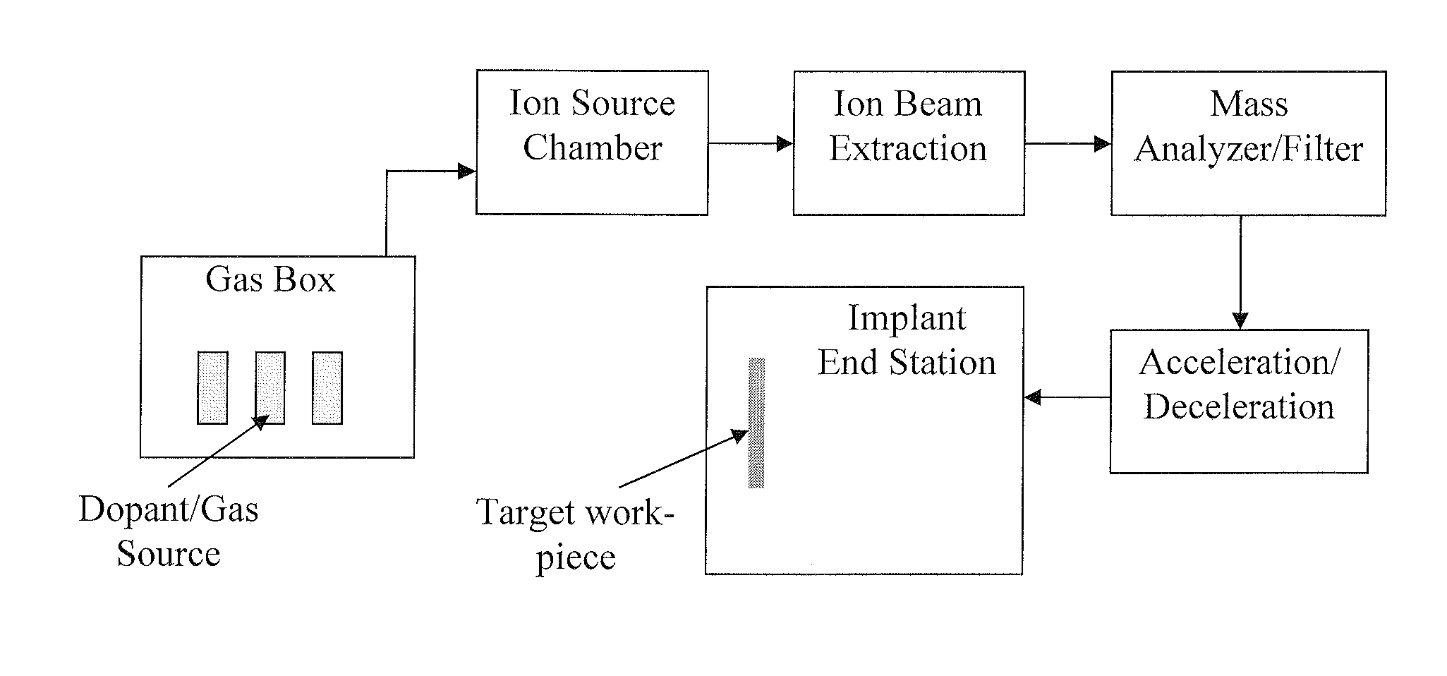
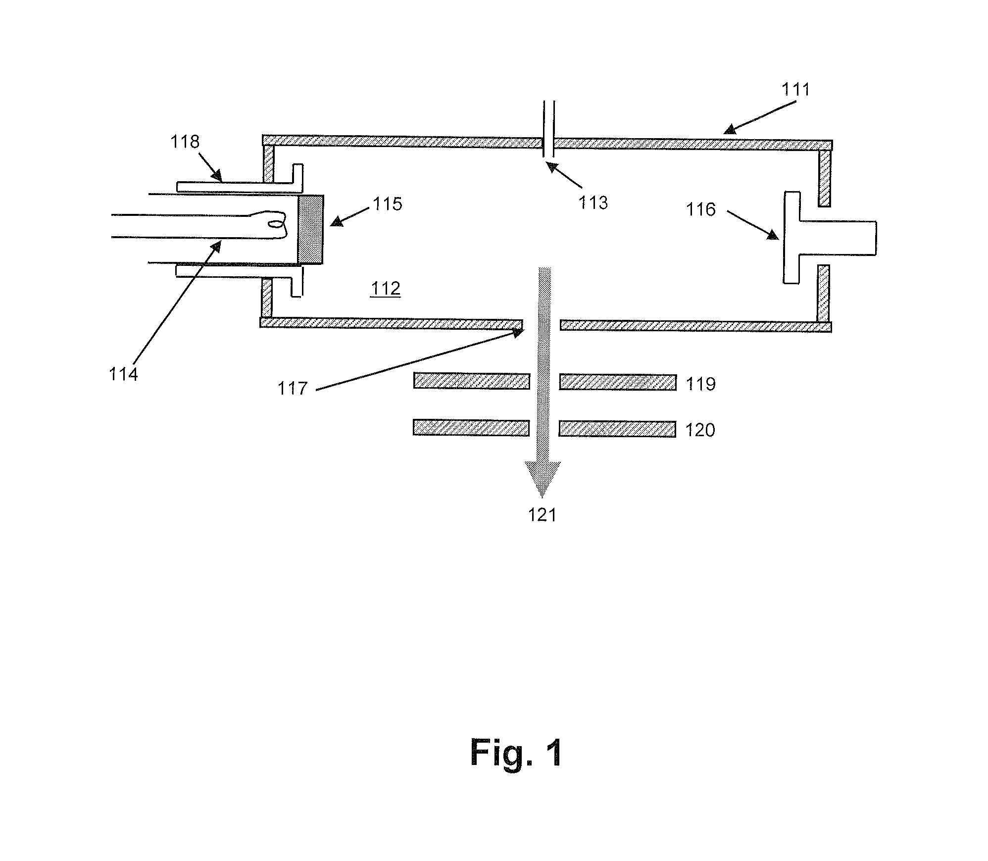
[0028]This invention is useful in the operation of ion implanters using heated cathode type ion source, such as the IHC (Indirectly Heated Cathode) ion source shown in FIG. 1. The ion source shown in FIG. 1 includes an arc chamber wall 111 defining the arc chamber 112. In the operation of the implanter, a source gas is introduced into the source chamber. The gases can be introduced into the source chamber, for example, through gas feed 113 at the side of the chamber. The ion source includes a filament 114. The filament typically is a tungsten-containing filament. For example, the filament may include tungsten or a tungsten alloy containing at least 50% tungsten. A current is applied to the...


PUM


Abstract

This invention relates in part to a method for preventing or reducing the formation and / or accumulation of deposits in an ion source component of an ion implanter used in semiconductor and microelectronic manufacturing. The ion source component includes an ionization chamber and one or more components contained within the ionization chamber. The method involves introducing into the ionization chamber a dopant gas, wherein the dopant gas has a composition sufficient to prevent or reduce the formation of fluorine ions / radicals during ionization. The dopant gas is then ionized under conditions sufficient to prevent or reduce the formation and / or accumulation of deposits on the interior of the ionization chamber and / or on the one or more components contained within the ionization chamber. The deposits adversely impact the normal operation of the ion implanter causing frequent down time and reducing tool utilization.

Description

RELATED APPLICATIONS[0001]The present application claims priority to U.S. Application Ser. No. 61 / 383,213, filed Sep. 15, 2010, which is incorporated by reference herein in its entirety.FIELD OF THE INVENTION[0002]This invention relates in part to a method for preventing or reducing the formation and / or accumulation of deposits in an ion source component of an ion implanter used in semiconductor and microelectronics manufacturing. The ion source component includes an ionization chamber and one or more components contained within the ionization chamber. The deposits adversely impact the normal operation of the ion implanter causing frequent down time and reducing tool utilization.BACKGROUND OF THE INVENTION[0003]Ion implantation is an important process in semiconductor / microelectronics manufacturing. The ion implantation process is used in integrated circuit fabrication to introduce dopant impurities into semiconductor wafers. The desired dopant impurities are introduced into semicon...

Claims


Application Information

Patent Timeline
Patent Type & Authority Applications(United States)
IPC IPC(8): H01J27/02
CPCH01J37/08H01J2237/022H01J37/3171H01J2237/002
Inventor SINHA, ASHWINIBROWN, LLOYD A.
Owner PRAXAIR TECH INC
Why Eureka
Try Eureka