
Split ring resonator creating a photonic metamaterial

a resonator and split-ring technology, applied in the direction of active medium materials, waveguide devices, lasers, etc., can solve the problems of increasing the difficulty of manipulating metal wires, weak coupling of ordinary non-magnetic materials to magnetic fields, and large losses of ferromagnetic materials

Active Publication Date: 2012-09-20
MILES TECH
View PDF2 Cites 22 Cited by
  • Summary
  • Abstract
  • Description
  • Claims
  • Application Information

AI Technical Summary

Benefits of technology

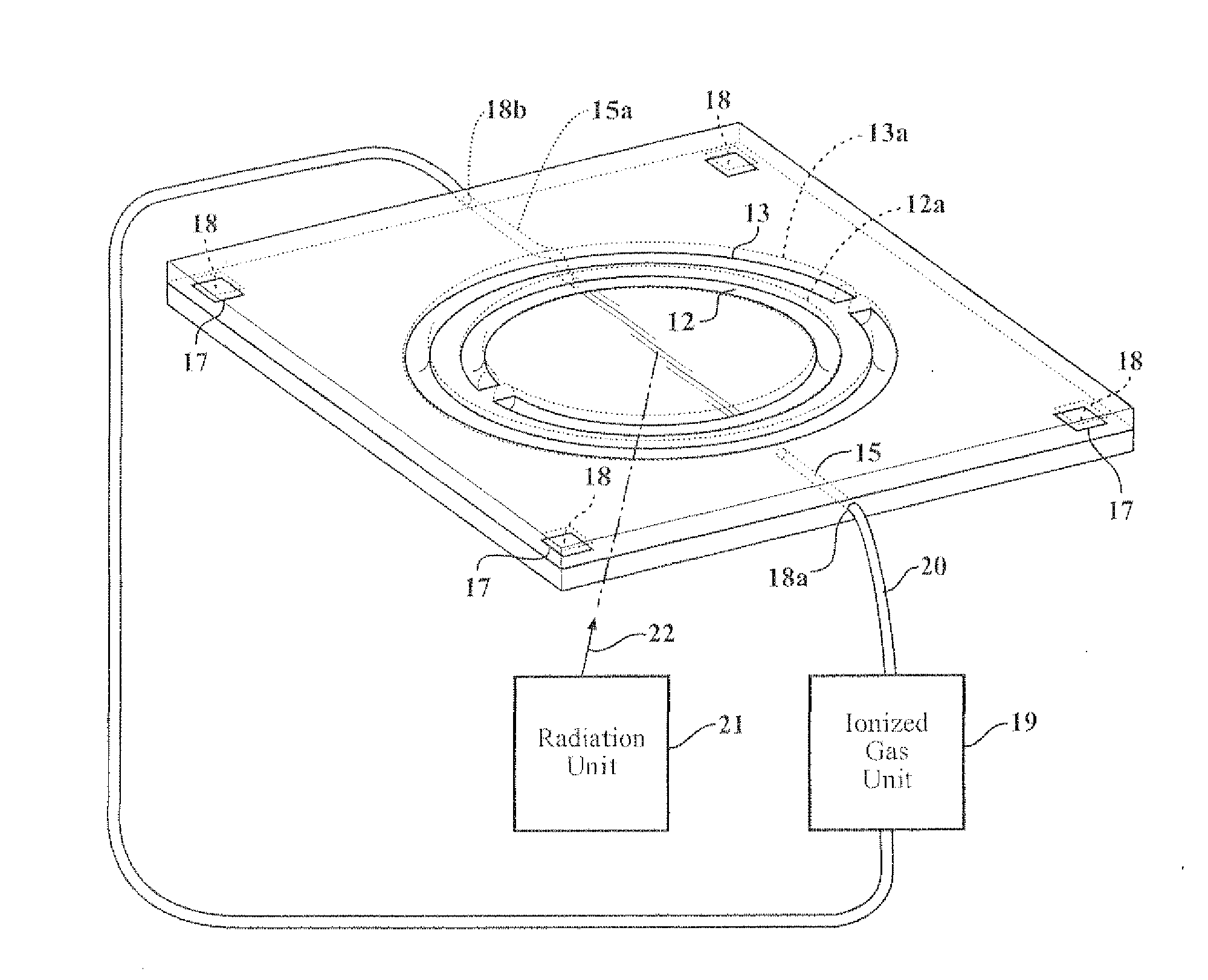
[0014]Aspects of the present invention provide a novel method and apparatus to create a split-ring resonator and related structures that operate at and interact with optical frequencies making a new approach to photonic metamaterials and the associated applications possible. To achieve this and other properties, aspects of the present invention create a split-ring resonator which employs an ionized or charged gas or beam, a plasma, or any similar type of a particle-level conductor confined in a small etching space or formed space of a substrate.

Problems solved by technology

For example, ordinary non-magnetic materials have extremely weak coupling to magnetic fields, and ferromagnetic materials have strong coupling but large losses.
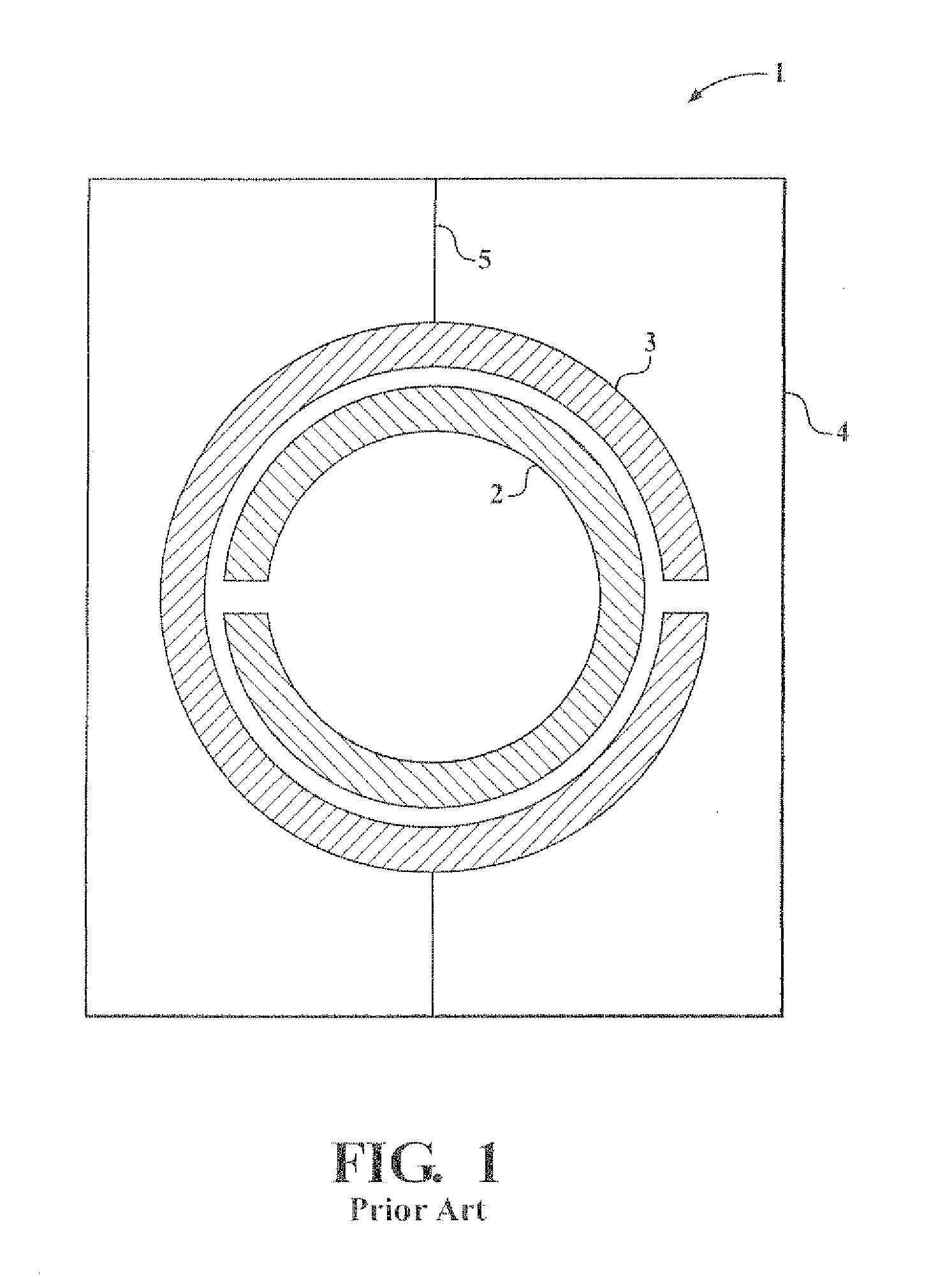
However, a problem with all of the conventional split-ring resonators in the related art is that these conventional split-ring resonators employ copper or some other metallic wire to form the split rings.
Metal wire is increasingly difficult to manipulate as the diameter or size decreases, and this presents a serious technical obstacle for creating split-ring resonators which will achieve a negative refractive index for higher frequency radiation, such as visible light, which has a wavelength range of about 380 nm-780 nm and a corresponding frequency ranging from about 430 trillion Hz (430 THz) to about 750 trillion Hz (750 THz).
In the related art, it has so far been impossible to design a split-ring resonator having the required inner radii to function at optical frequencies using conventional structures, such as copper split-rings.
As a result, it has also been impossible to achieve the numerous potential benefits that would result from being able to manipulate higher frequency radiation with a negative index of refraction material, such as sub-wavelength resolution optics, optical cloaking, ultra-high efficiency detection, and likely applications for more powerful communications and computing.
Additional problems occur using metallic split-ring resonators.
For example, naturally paramagnetic and ferromagnetic materials only achieve strong coupling to magnetic fields that have significant losses.

Method used


Image

  • Split ring resonator creating a photonic metamaterial
  • Split ring resonator creating a photonic metamaterial
  • Split ring resonator creating a photonic metamaterial

Examples


Embodiment Construction

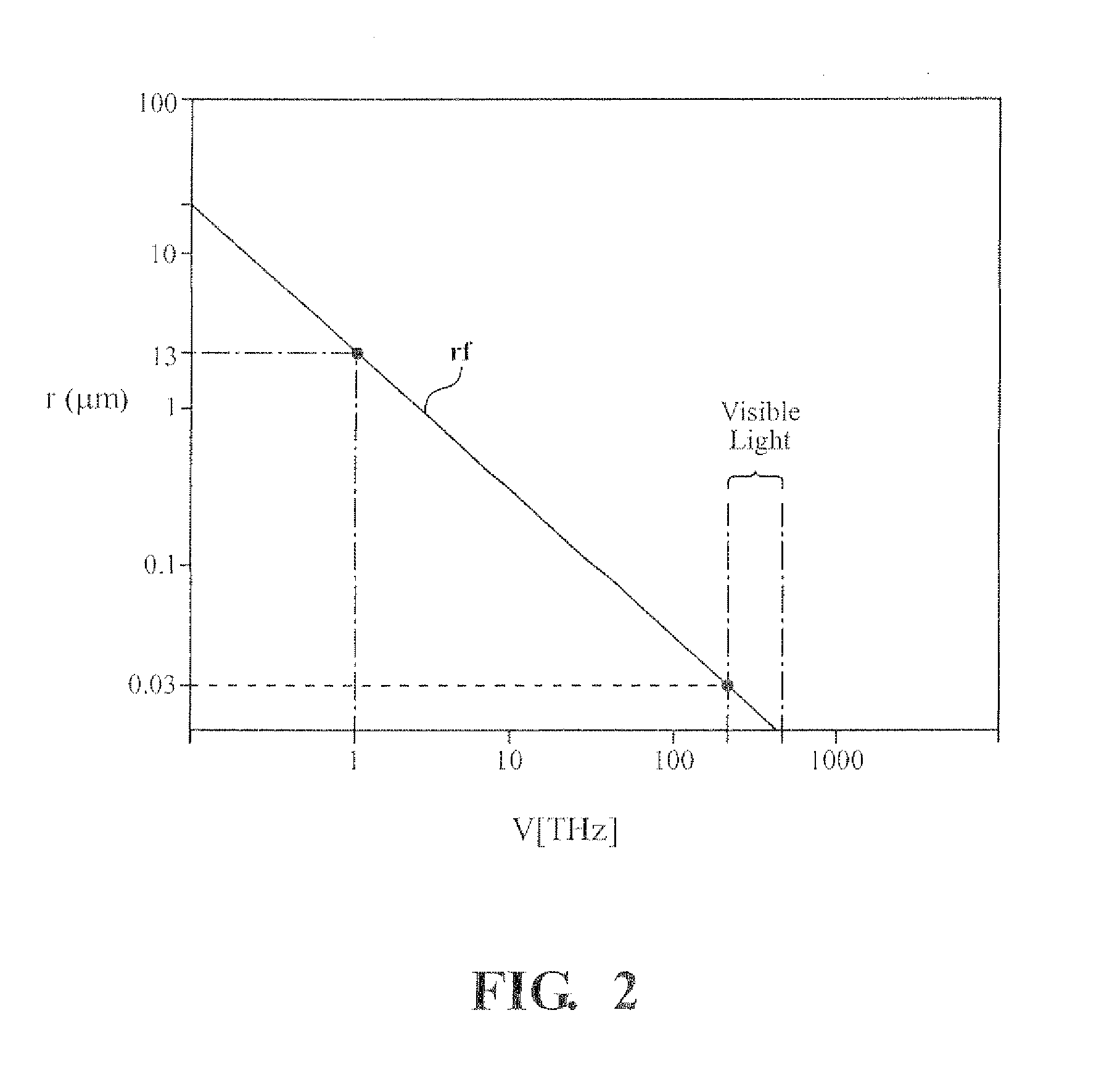
[0048]A basic concept of aspects of the present invention is to employ ionized or charged gas, beam, or plasma, or any similar type of a particle-level nonmagnetic conductor in place of conventional metallic rings, into a very finely etched or formed space of a substrate to achieve a split-ring resonator (SRR) with a diameter substantially smaller than SRRs of the related art. In doing so, the SRR according to aspects of the present invention achieves a myriad of benefits not achieved by conventional SRRs, such as the manipulation of visible light and even higher frequency radiation. The SRR according to aspects of the present invention can be used to wirelessly transmit energy, encoded data, communication signals, and many other types of radiation in advantageous ways.

[0049]FIG. 2 depicts the relationship between the inner radii of a SRR and the frequency of radiation to achieve a resonant frequency rf. In FIG. 2, the vertical column on the left-hand side of FIG. 2 corresponds to t...


PUM


Abstract

A split ring-resonator includes a substrate, an inner-trench or cavity formed into the substrate, the inner trench or cavity including a split, and an outer trench or cavity formed into the substrate around the inner trench or cavity, the outer trench or cavity including another split disposed at an opposite end of the split in the inner trench or cavity, wherein the inner trench or cavity and the outer trench or cavity are configured to receive an electrically conductive gas and / or plasma to form a split-ring resonator,

Description

CROSS-REFERENCE TO RELATED APPLICATIONS[0001]This application is a national stage of PCT / US2011 / 028432, filed on Mar. 15, 2011, which is based on U.S. provisional application no. 61 / 732,689, filed Aug. 11, 2010, the entire contents of which are incorporated herein by references.FIELD OF THE INVENTION[0002]Aspects of the present invention relate to a split-ring resonator which employs an ionized or charged gas, beam, or plasma or any similar type of a particle-level conductor, and more particularly, to a split-ring resonator which employs an ionized or charged gas, beam, or plasma or any similar type of a particle-level conductor to create a photonic metamaterial interacting with or operating at optical frequencies, such as terahertz (THz), infrared, or visible light.BACKGROUND OF THE INVENTION[0003]Recently, materials known as “metamaterials” have been discovered. Metamaterials include a type of artificial structure, referred to as a “left-handed medium” (LHM), which is characterize...

Claims


Application Information

Patent Timeline
IPC IPC(8): H01S3/22H01L33/00
CPCH01P7/08
Inventor MILES, PATRICK ALLEN
Owner MILES TECH
Learn More