Separation Vessels For Use In Polymerization Processes And Methods For Cleaning Same

a separation vessel and polymerization process technology, applied in the direction of cleaning hollow articles, chemical/physical/physical-chemical processes, chemistry apparatus and processes, etc., can solve the problems of reducing the cleaning efficiency of the separation vessel, affecting the cleaning effect, and affecting the appearance and film properties of the final polyethylene product, so as to achieve a more thorough cleaning, reduce the number of vessel cleanings, and promote a higher degree of flow

Inactive Publication Date: 2012-09-27
EXXONMOBIL CHEM PAT INC
View PDF11 Cites 14 Cited by
  • Summary
  • Abstract
  • Description
  • Claims
  • Application Information

AI Technical Summary

Benefits of technology

[0005]Clearly, there is a need for an improved cleaning technique for a low pressure separator vessel that is faster and that reduces the amount of downtime of the polymerization plant. Ideally, such a technique would be easier and less expensive to implement, and would reduce the amount of downtime for cleaning operations necessary to maintain a high quality polyethylene product.
[0008]The cleaning process of the invention requires only about 2 hours to perform, in contrast to the full day required by the prior art method. Moreover, the invention obviates the need for two separate low pressure separator vessels, and does not require disconnection and lifting and lowering steps that can damage the vessel. Finally, the polytetrafluoroethylene lining that covers the interior surfaces of the vessel and, optionally, the cover, not only results in more thorough cleaning when the polyethylene skin is lifted off of the interior surfaces, but also promotes a higher degree of flow on the inner surfaces of the vessel during the manufacture of the polyethylene, thus reducing the number of vessel cleanings required to maintain a high quality product.

Problems solved by technology

The lower pressure in this vessel results in the flashing away of the remainder of the unreacted ethylene from the product.
The applicants have observed that the non-Newtonian characteristics of the liquid polyethylene flowing through the low pressure separator vessel results in a very slow flow rate at the interface between the liquid polyethylene and inner surface of the vessel.
If these degraded polymers are not periodically removed from the inner surfaces of the low pressure separator vessel, they can contaminate the final polyethylene product and degrade its appearance and film properties.
The problem is worse in situations where a high clarity and purity polyethylene product is essential for the rendering of a particular final product, such as blown film products, medical applications and sensitive electrical applications.
Unfortunately, such a vessel replacement procedure still takes about a day to implement due to the time required to (1) mechanically disconnect all of the interfaces of the fouled vessel with the other components of the polymerization plant, (2) exchange the multi-ton fouled vessel with a multi-ton cleaned vessel and (3) to re-connect all of the interfaces between the clean vessel and the polymerization plant.
Moreover, as the vessel weighs one or more tons, the step of exchanging the fouled vessel with a cleaned vessel must be done by way of a slow and delicate crane operation in order to avoid breakage or damage to the valves, pipes and other interface fittings that must be disconnected and reconnected.

Method used


Image

  • Separation Vessels For Use In Polymerization Processes And Methods For Cleaning Same
  • Separation Vessels For Use In Polymerization Processes And Methods For Cleaning Same
  • Separation Vessels For Use In Polymerization Processes And Methods For Cleaning Same

Examples


Embodiment Construction

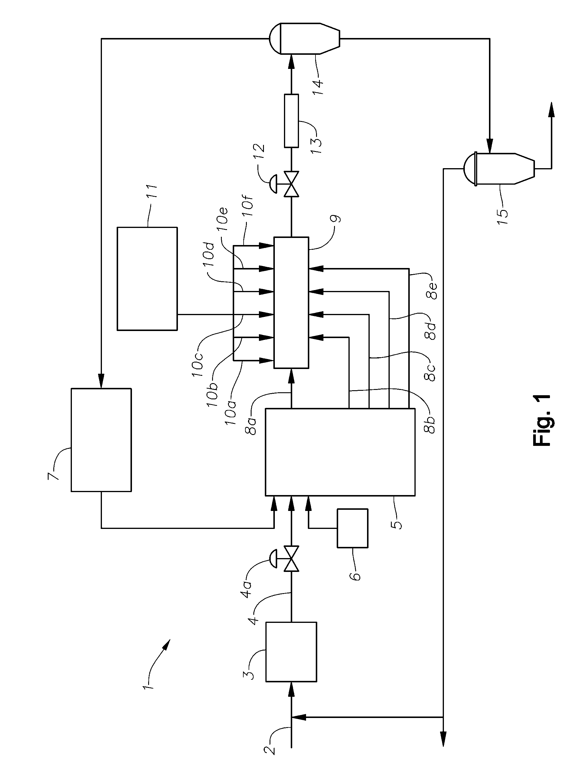
[0021]FIG. 1 is a schematic of a polymerization plant 1 of the type that includes the low pressure separator vessel 15 that the cleaning system and method are applied to. The low pressure separator vessel typically operates at a pressure in the range of from 0.1 to 20 barg, more preferably from 0.1 to 5 barg, yet more preferably from 0.1 to 2 barg and especially preferably from 0.1 to 0.9 barg (barg=bar gauge, that is, pressure in excess of atmospheric). The plant 1 includes an ethylene feed line 2 which supplies fresh ethylene to a primary compressor 3. The ethylene discharged from the primary compressor 3 flows via conduit 4 having a valve 4a to a secondary compressor 5. Also entering the secondary compressor 5 is a stream of fresh modifier(s) and / or optional comonomer(s) and a stream of recycled ethylene. The fresh modifier stream is supplied by a separate modifier pump 6. The recycled ethylene comes from the high pressure recycle system 7.

[0022]The secondary compressor 5 dischar...


PUM

PropertyMeasurementUnit
thicknessaaaaaaaaaa
thicknessaaaaaaaaaa
thickaaaaaaaaaa

Abstract

Both a system and method for cleaning a low pressure separation vessel of a high pressure polyethylene polymerization plant are provided. The system includes a polytetrafluoroethylene lining that covers the interior surfaces of the vessel, and a cover mounting assembly including an annular clamp for detachably mounting a cover over the vessel. The mounting assembly includes a clamp actuator for quickly securing and releasing the cover with respect to a top rim of the vessel. The vessel is drained of liquid polyethylene and allowed to cool to ambient temperature, thus creating a frozen “skin” of polyethylene around the interior surfaces of the vessel. The clamp actuator releases the cover. The polyethylene skin is peeled off the interior sides the vessel and gathered up at the top to form a neck, thus peeling the polyethylene skin away from the polytetrafluoroethylene lining along with any degraded polymers or other impurities that have accumulated on the interior surfaces of the vessel.

Description

FIELD OF THE INVENTION[0001]This invention generally relates to a high pressure polymerization process for the manufacture of polyethylene, and is specifically concerned with a system and method for cleaning a low pressure separation vessel of a polyethylene polymerization plant that provides rapid and effective in situ removal of impurities that accumulate within the vessel.BACKGROUND OF THE INVENTION[0002]In the manufacture of ethylene polymers, ethylene gas is compressed into a supercritical fluid and then heated. The hot supercritical ethylene is then admitted into a tubular polymerization reactor, along with a supply of a chemical initiator and a modifier. The chemical initiator initiates polymerization of the free radical ethylene, while the modifier controls the molecular weight of the resulting polyethylene. Since only about 40% of the ethylene monomers react, the resulting polyethylene product that is discharged from the reactor is a mixture of ethylene polymers intermixed ...

Claims


Application Information

Patent Timeline
Patent Type & Authority Applications(United States)
IPC IPC(8): B01J19/00B08B9/08
CPCB01J3/03B01J19/02B01J2219/0245B01J2219/1946C08F10/00C08F2/007B08B1/005C08F110/02
Inventor CORNELISSEN, PHILIP HENRILAMMENS, HENRI AIMECIANCIO, FAUSTOMORGAN, CHRISTOPHER K.REYNDERS, LEO
Owner EXXONMOBIL CHEM PAT INC
Why Eureka
Try Eureka