Seismic streamer formed of sections comprising a main sheath covered with an external sheath formed using a thermoplastic material loaded with a biocide material

a streamer and thermoplastic material technology, applied in seismology, seismic analysis, instruments, etc., to avoid a substantial increase in the weight of seismic streamers and be less costly

Inactive Publication Date: 2012-09-27
SERCEL INC
View PDF7 Cites 15 Cited by
  • Summary
  • Abstract
  • Description
  • Claims
  • Application Information

AI Technical Summary

Benefits of technology

[0020]The invention in particular has for objective to overcome these disadvantages of prior art. More precisely, the invention has for objective to propose a technique making it possible for a seismic streamer to resist the fouling by bio-fouling, that can be implemented using industrial processes that are in particular less costly compared to the techniques mentioned in reference to prior art. The invention also has for objective to provide such a technique that is compatible with the mechanical constraints linked with seismic streamers, in particular in relation to their capacity of being wound. The invention also has for objective to provide such a technique that is compatible with the internal components of seismic streamers, entailing in particular components transporting an electrical current. The invention also has for objective to provide such a technique which avoids a substantial increase in weight of the seismic streamers.

Problems solved by technology

In addition, even in the case of unfavourable weather conditions, it is avoided, as much as possible, to return the streamers to the vessel, as the operations of returning / deploying are in practice particularly tedious and long.
Therefore, the tubular structure of the streamers is subject to fouling, in particular due to the proliferation, on the external layer of the seismic streamers, of microorganisms or bio-fouling.
However, these bio-fouling generate in time several disadvantages, among which:they generate hydrodynamic flow noise: the proliferation of the bio-fouling can result in the formation on the external layer of the seismic streamers of amalgams or incrustations likely to disturb the measurements to be carried out;they tend to increase the drag of seismic streamers and, consequently, the consumption in fuel of the boat that is tugging them;during the winding of seismic streamers on the winches of the tug boat, the bio-fouling is deposited and fouls the equipment, and generate, after a few days, a stench due to their degradation in the air;certain types of bio-fouling have a shell that can pierce the sheaths of the seismic streamers, which can give rise to water intake inside the seismic streamer, or to an oil leak (in the case of a seismic streamer incorporating a filling fluid, such as kerosene).
Such devices have been experimented with, and then abandoned in practice, due to their cost and especially due to the fact that, most of the time, become separated from the seismic streamers and become lost in the sea beds.
However, “anti-fouling” paints generally contain TBT (tributyltin) which is now well known for its toxicity.
Such paints are therefore unacceptable from an environmental standpoint (pollution of sea water) as well as in relation to the safety of persons likely to be in contact with TBT paint during the manipulation of seismic streamers.
Furthermore, the techniques for applying “anti-fouling” paint are hardly compatible with the technical and economical constraints linked with seismic streamers.
In this case, the projection operation is particularly long and costly due to the high number of kilometres of streamers to be treated.
In addition, it is necessary to comply with a drying time for the paint, which implies storing the seismic streamers in positions that take up a considerable amount of space in order to avoid any contact of the portions of treated streamers with themselves (which excludes the winding of seismic streamers); such storage is consequently not viable economically.
Such a technique thus makes it possible to overcome the problems of storage of seismic streamers during the drying phase of the paint, but implies very high implementation costs.
Indeed, the equipment costs for boats are substantial in the sense where it is necessary to provide as many projection rings as there are winches for winding seismic streamers (up to twelve winches can be mounted on a seismic prospection boat).

Method used


Image

  • Seismic streamer formed of sections comprising a main sheath covered with an external sheath formed using a thermoplastic material loaded with a biocide material
  • Seismic streamer formed of sections comprising a main sheath covered with an external sheath formed using a thermoplastic material loaded with a biocide material

Examples


Embodiment Construction

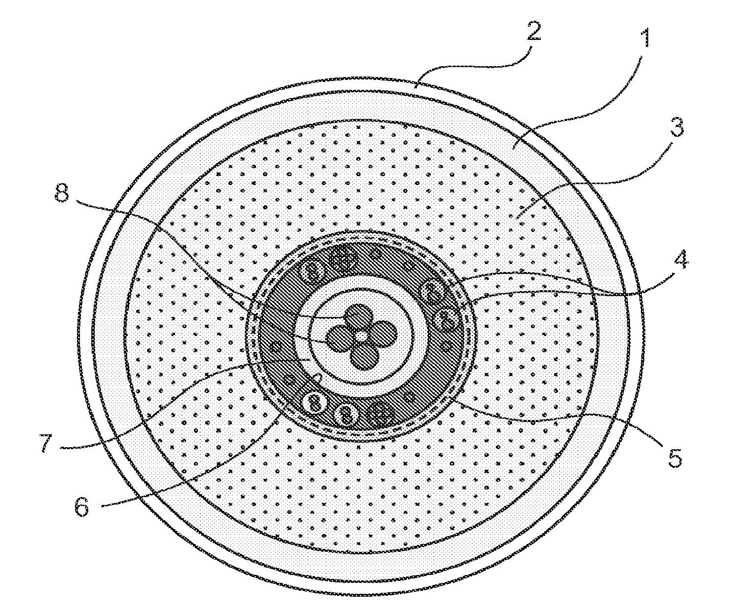
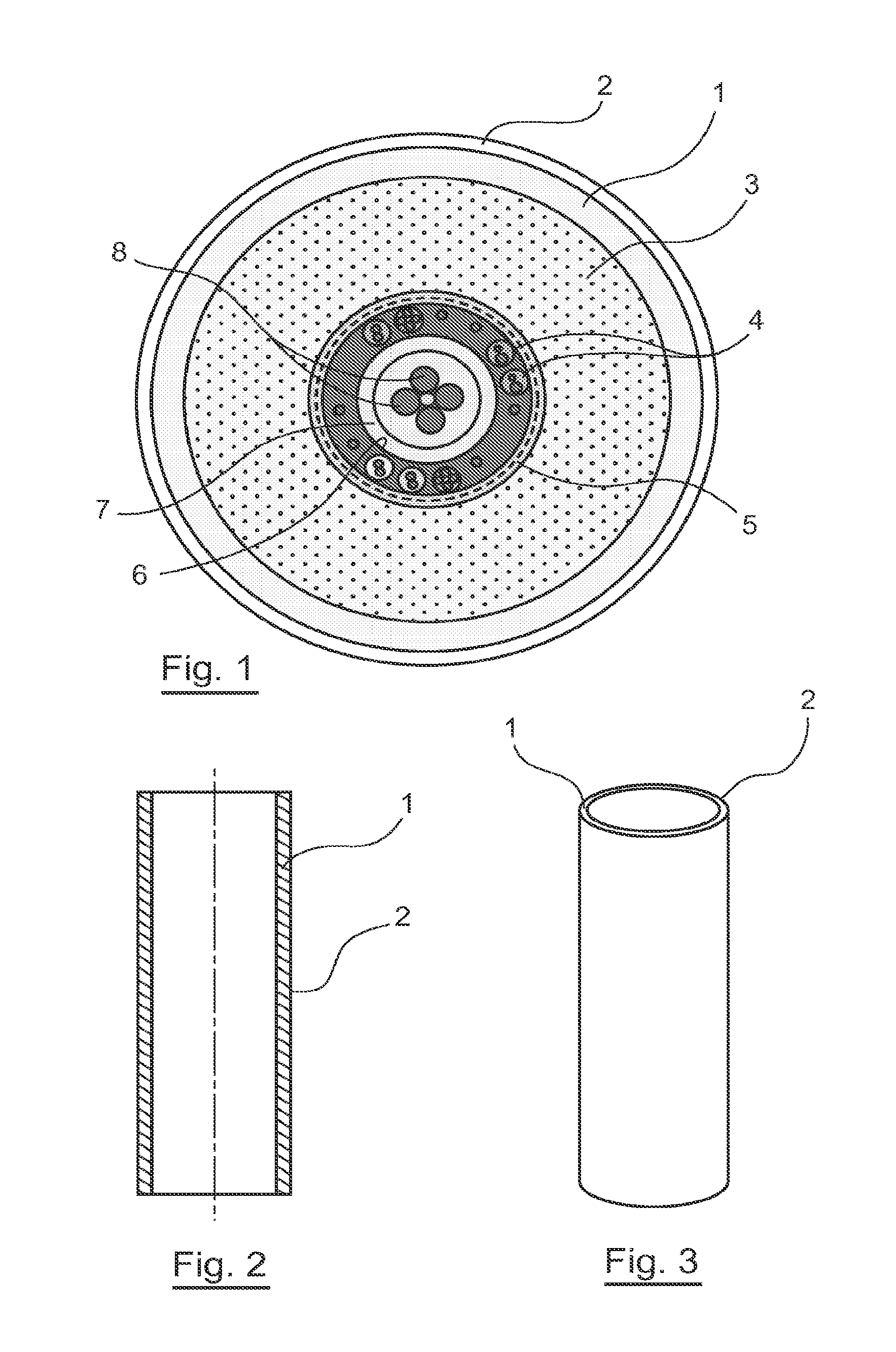
[0048]The principle of the invention resides in the proposing of a seismic streamer wherein sections having a protection against bio-fouling, this protection taking the form of an external sheath added onto the main sheath of the sections, this external sheath being formed using a thermoplastic material loaded with a biocide material.

[0049]In reference to FIGS. 2 and 3, a section (or tubular element) of a seismic streamer includes a main sheath 1 delimiting a body wherein are mounted hydrophones, power cables and data transmission cables. An external sheath 2 is added to the main sheath 1 in such a way as to coat the latter.

[0050]Note that a section of seismic streamer generally has a length of 150 meters, the seismic streamer able to have a total length of approximately 12 kilometres.

[0051]Within the framework of the invention, the seismic streamer can be indifferently of the “fluid” type or “solid” type or any other seismic streamer filling technology such as gel. Recall that a se...


PUM


Abstract

System and method for providing an anti-fouling function to a streamer to be towed under water for seismic survey data collection. The method includes mixing a thermoplastic material with a biocide material to form an external sheath material; and forming an external sheath over a main sheath of the streamer to provide the anti-fouling function. The external sheath is formed from the external sheath material such that the biocide material is distributed throughout the external sheath.

Description

CROSS-REFERENCE TO RELATED APPLICATIONS[0001]This application is a Divisional of co-pending application Ser. No. 12 / 509,266, filed on Jul. 24, 2009, which claims priority to Application No. 08 / 04282 filed in France on Jul. 28, 2008, the entire contents of which are hereby incorporated by reference into the present application and for which priority is claimed under 35 U.S.C. §120.BACKGROUND OF THE INVENTION[0002]1. Field of the Invention[0003]The field of the invention is that of the acquisition of seismic data. More precisely, the invention relates to equipment for analysing sea beds. The invention in particular relates to the industry of oil prospection via the seismic method, but can be applied to any field implementing a seismic data acquisition network in a marine environment.[0004]2. Background of the Invention[0005]The operations of acquiring, in the field, geophysical data, conventionally implement networks of sensors. These sensors are most often hydrophones; however said o...

Claims


Application Information

Patent Timeline
Patent Type & Authority Applications(United States)
IPC IPC(8): G01V1/38B05D1/26G01V1/16
CPCG01V1/201G01V1/3843G01V1/38
Inventor VIGNAUX, JEAN-JACQUES
Owner SERCEL INC
Why Eureka
Try Eureka