Glucose Monitoring System

a monitoring system and glucose technology, applied in the field of body fluid sampling/fluid delivery devices, can solve the problems of multiple strikes of devices due to recoil, mechanical launchers are unlikely to provide integrated sample acquisition means, and the lancing process cannot be combined with the sample acquisition and testing step, etc., to achieve the effect of reducing or eliminating pain

Inactive Publication Date: 2012-09-27
BLACK MICHAEL DARRYL +2
View PDF4 Cites 33 Cited by
  • Summary
  • Abstract
  • Description
  • Claims
  • Application Information

AI Technical Summary

Benefits of technology

[0022]In another embodiment, a method of sampling a body fluid at a tissue site provides one or more microneedles, each of a microneedle having a height of 500 μm 50 mm, and a variable tapering angle of 60 to 90°. The ...

Problems solved by technology

Such devices have the possibility of multiple strikes due to recoil, in addition to vibratory stimulation of the skin as the driver impacts the end of the launcher stop, and only allow for rough control for skin thickness variation.
When using existing methods, blood often flows from the cut blood vessels but is then trap...

Method used


Image

  • Glucose Monitoring System
  • Glucose Monitoring System
  • Glucose Monitoring System

Examples


example 1

[0129]In one embodiment of a mass fabrication method for microneedle array 14 formation, anisotropic reactive ion etching techniques were used with polymeric material are etched with controllable sidewall roughness and anisotropy as well as high etch mask selectivity.

[0130]The fabrication of multiple microneedles 14 was done on a wafer level, similar to the fabrication of IC chips. FIG. 9 shows a double side polished polymer wafer and etch-through holes on the wafer. A total of about 250 patches 12 on one 6″ diameter wafer were batch fabricated, providing a yield of 75%.

[0131]The fabrication of multiple microneedles 14 was done on a wafer level, similar to the fabrication of IC chips. FIG. 9 shows a double side polished polymer wafer and etch-through holes on a polymer wafer. A total of about 250 patches 12 on one 6″ diameter wafer were batch fabricated, providing a yield of 75%.

[0132]FIG. 10 shows the main batch process steps. The series of images on the left indicate the progressi...

example 2

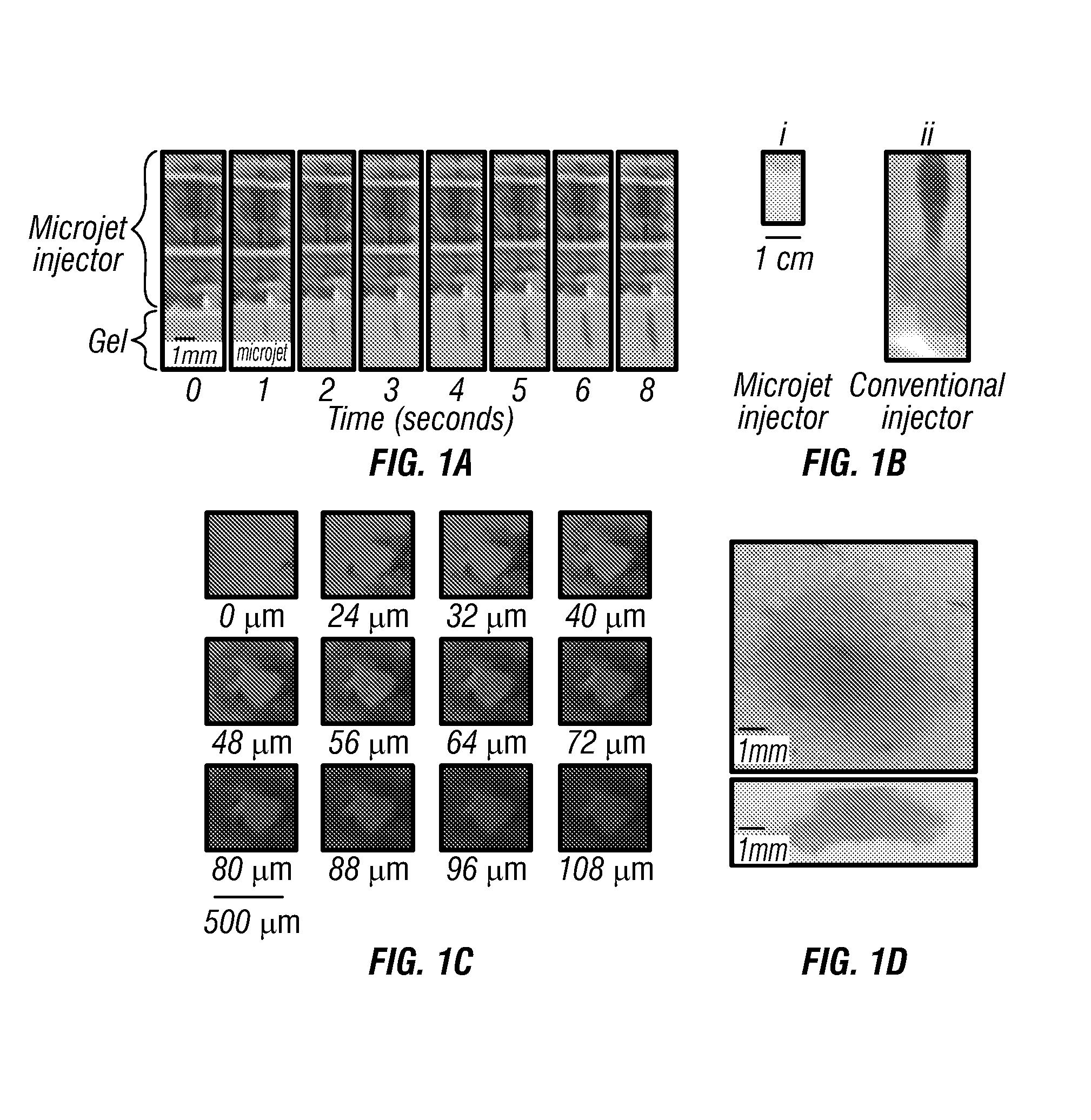
[0145]As a non-limiting example, a rise time of 10 ps lead to a mean velocity of 127 m / s for a 10-nanoliter microjet delivered from a -pm diameter micronozzle (v=Q / At, where Q is the microjet volume, A is the cross-sectional area of the micronozzle, and t is the rise time). Formation of microjets was confirmed by using high-speed photography and strobe microscopy.

[0146]By controlling the amplitude and rise time of the pulse, velocity as well as volume of the microjet was adjusted. The dispensed volume from the nozzle was replaced by liquid from a reservoir 18 that is maintained under slight positive pressure to avoid backflow.

[0147]FIG. 11 illustrates one embodiment of performance characteristics of the pulsed microjet injector. As shown, there can be a dependence of microjet volume on voltage applied across the piezoelectric crystal.

example 3

[0148]A microjet volume of 15 n1 was used for most experiments reported in this study. (b) Dependence of total microjet volume ejected in air as a function of time. The device was operated at a voltage of 140 V across the crystal at a frequency of 1 Hz, n=3; error bars correspond to SD.

[0149]Microjets were ejected from the micronozzle at exit velocities exceeding m / s and volumes of 10 to 15 nanoliters. The microjets were cylindrical in shape and each jet pulse could be clearly distinguished. To deliver volumes in excess of 10 to 15 nanoliters, the microjets were created over a prolonged period and the total amount of liquid ejected was proportional to the application time (FIG. 3b; determined with a radiolabeled tracer). For data in FIG. 3b, a pulsation frequency of 1 Hz (1 microjet per second) was used. This frequency could be increased if higher delivery rates are desired.


PUM


Abstract

A body fluid sampling system for use on a tissue site includes a drive force generator and one or more microneedles operatively coupled to the drive force generator. Each of a microneedle has a height of 500 to 2000 μm and a variable tapering angle of 60 to 90°. A sample chamber is coupled to the one or more microneedles. A body fluid is created when the one or more microneedles pierces a tissue site flows to the sample chamber for glucose detection and analysis.

Description

CROSS-REFERENCE TO RELATED APPLICATION[0001]This application is a continuation in part of U.S. Ser. No. 13 / 052,887 filed Mar. 21, 2011, which application is fully incorporated herein by reference.BACKGROUND[0002]1. Field of the Invention[0003]This invention relates generally to body fluid sampling / fluid delivery devices, and more particularly to glucose monitoring and sampling.[0004]2. Description of the Related Art[0005]Lancing devices are known in the medical health-care products industry for piercing the skin to produce blood for analysis. Biochemical analysis of blood samples is a diagnostic tool for determining clinical information. Many point-of-care tests are performed using whole blood, the most common being monitoring diabetic blood glucose level. Other uses for this method include the analysis of oxygen and coagulation based on Prothrombin time measurement. Typically, a drop of blood for this type of analysis is obtained by making a small incision in the fingertip, creatin...

Claims


Application Information

Patent Timeline
IPC IPC(8): A61B5/157
CPCA61B5/1468A61B5/14514A61B5/157A61B10/0045A61B17/205A61B2010/008A61M5/204A61M5/30A61M37/0015A61M2037/0023A61M2037/003A61M2037/0046A61M2037/0061G06F19/3406A61B5/151A61B5/150022A61B5/15003A61B5/150167A61B5/150175A61B5/150282A61B5/150358A61B5/150984G16H40/63
Inventor BLACK, MICHAEL DARRYLCHAMBERS, ANITA MARGARETTEHUANG, TRENT
Owner BLACK MICHAEL DARRYL
Why Eureka
Try Eureka