
Coordinate measuring device having positional change sensors

Inactive Publication Date: 2012-10-04
CARL ZEISS IND MESSTECHN GMBH
View PDF20 Cites 43 Cited by
  • Summary
  • Abstract
  • Description
  • Claims
  • Application Information

AI Technical Summary

Benefits of technology

[0033]To detect collisions, it is possible to use all accelerations that are greater than the maximum machine acceleration. If, in addition, the measurement unit is further supplied with information as to which acceleration is currently being conducted, the coordinate measuring machine can detect a deviation in direction and / or amplitude as a possible collision, and thus immediately bring the machine into a safe state, for example effect free-running of the appropriate axis, or stop the movement of the coordinate measuring machine.
[0035]Thus, the signals detected by means of the position change sensors can be used in order to determine the instantaneous position and orientation of the sensor, to monitor the drive behavior of the coordinate measuring machine with reference to the acceleration and / or speed actually active at the sensor, and to monitor discontinuities in the drive behavior, for example jerking, slipping or frequency excitations. In particular, it is thus rendered possible to optimize the drive behavior of the entire coordinate measuring machine in a self-learning fashion so as to arrive at an optimum measurement performance with reference to accuracy and / or speed. Since actual accelerations at the sensor are known, it is possible to dispense with a complicated development of model parameters for the coordinate measuring machine. In addition, the coordinate measuring machine can optimize itself with the aid of the actual acceleration data. Furthermore, it is thus also possible to avoid problems in the modeling such as, for example, a manufacturing tolerance, where prescribed fixed parameter sets do not lead to satisfactory results.
[0042]In this way, it is possible for the movement profile of the coordinate measuring machine actually to be determined during the recording of measurement data by means of an optical sensor, for example during an exposure time of the optical sensor. Typical exposure times lie in the range from 10 to 20 ms for normal frame rates of 50 Hz. This corresponds to only individual or a few system clocks. The recorded image is smeared by the movement during the image recording and appears unsharp. This effect can now be corrected subsequently, since it is possible to directly determine the actual movement path of the sensor, at least its relative path between the start and end of the exposure time. It is obvious that the computational correction can be performed more effectively, the more accurately it is possible to determine the data of the movement path. The direct detection of the change in position is much superior in this case to the determination of position change data by differentiation of the position data.
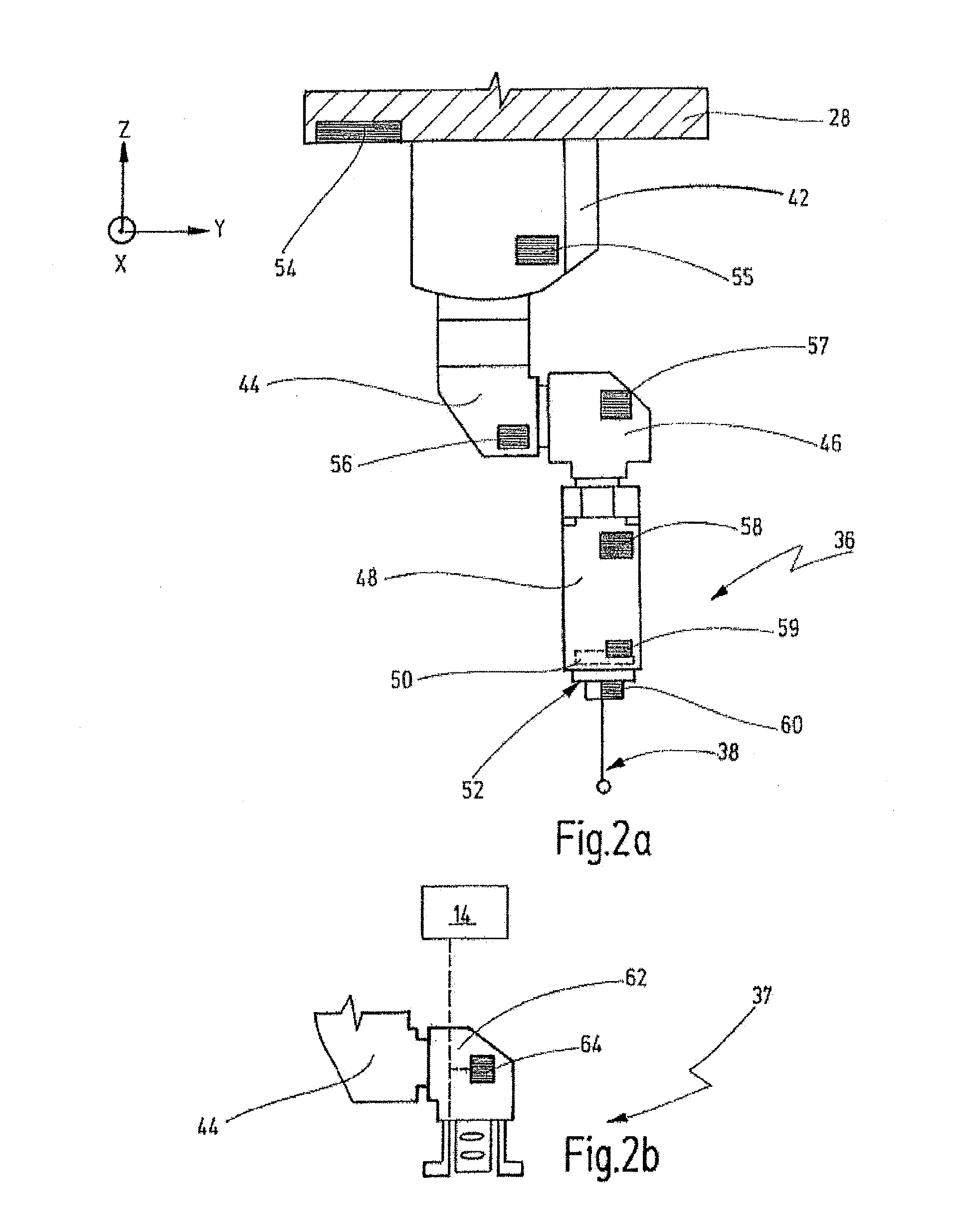
[0054]For application in coordinate measuring machines having tactile sensors, it is helpful, for example, when the mutually displaceable parts in a probe head, for example the housing and the feeler holder, are separately equipped with position change sensors in each case. It is thereby possible to detect touching earlier from the difference between the corresponding measurement signals of the first and second sensors. It is particularly advantageous that the measurement rate of the position change sensors can be performed independently and therefore at a higher frequency than the measurement of the position of the coordinate measuring machine from which differentiated previously acceleration data were obtained.
[0056]It can be provided to check an acceleration measurement at regular intervals, in particular at a multiple of the system clock. This can be performed by updating the acceleration and integrating it to the appropriate speed, and further integrating it to the appropriate position. The position data thus obtained can then, for example, be compared with the data of the position sensors of the coordinate measuring machine that directly determine the position of the sensor in three spatial directions. It is thereby possible to prevent the measurements from drifting apart and to achieve more stable data as well as a reliable measurement.
[0057]It can then be provided in the case of the method for collision detection of a coordinate measuring machine that the desired value is a maximum value fixed for the coordinate measuring machine, and that the putting-into-a-safe-state is performed if the at least one change in position is greater than the maximum value. Alternatively, the maximum value can also be updated dynamically by a control unit of the coordinate measuring machine, for example as it occurs in the desired movement path. It is possible to provide a safety margin in order to avoid erroneous estimates.

Problems solved by technology

However, optical sensors encounter limits when objects of complex shapes are to be measured, since what can then happen is that details of the object do not lie in an image recording area of the optical sensor, and therefore cannot be detected.
With tactile sensors, movements of the sensor during touching or probing can lead to distortions that necessarily must be taken into account in an evaluation of the measurement results.
For optical sensors, for example for CCD cameras, a movement during the measurement operation leads to a “smearing” of the recorded image which then appears unsharp.
Although it is possible to eliminate from the measurement result the movement of a sensor during the measurement operation by subsequent computational after processing, it is at the expense of absolutely requiring adequately exact knowledge of the movement operation and / or the path data of the sensor during measurement.
In this case, however, the speed or the acceleration of the sensor or of the housing structure is not acquired directly.
Because of the limited resolution, discontinuous changes such as arise in the event of mechanical probing and / or collision also can only be detected with difficulty at present or must have a certain minimum size in order to be detected.
Consequently, a distortion of the system can give rise to tilt errors during measurement, and dynamic effects can be taken into account only conditionally.

Method used


Image

  • Coordinate measuring device having positional change sensors
  • Coordinate measuring device having positional change sensors
  • Coordinate measuring device having positional change sensors

Examples


Embodiment Construction

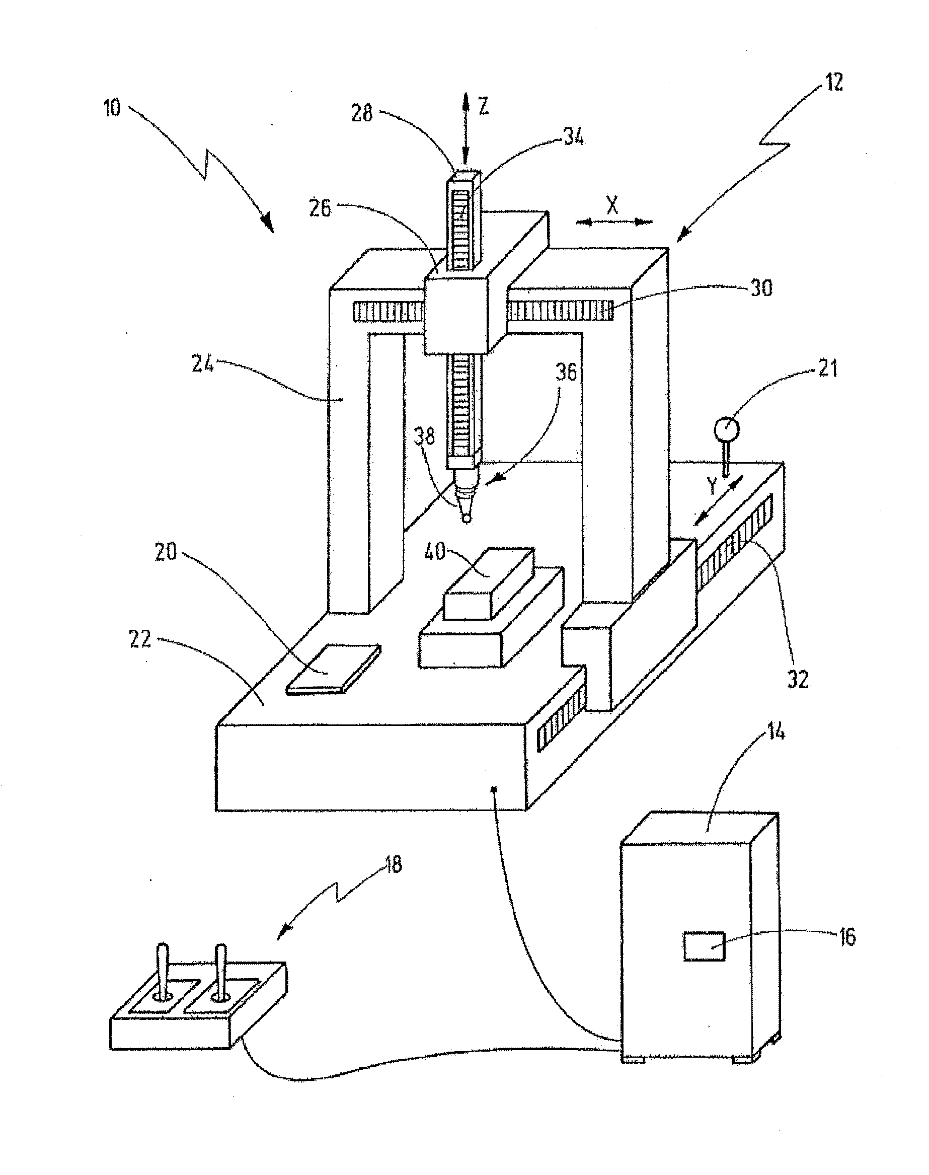
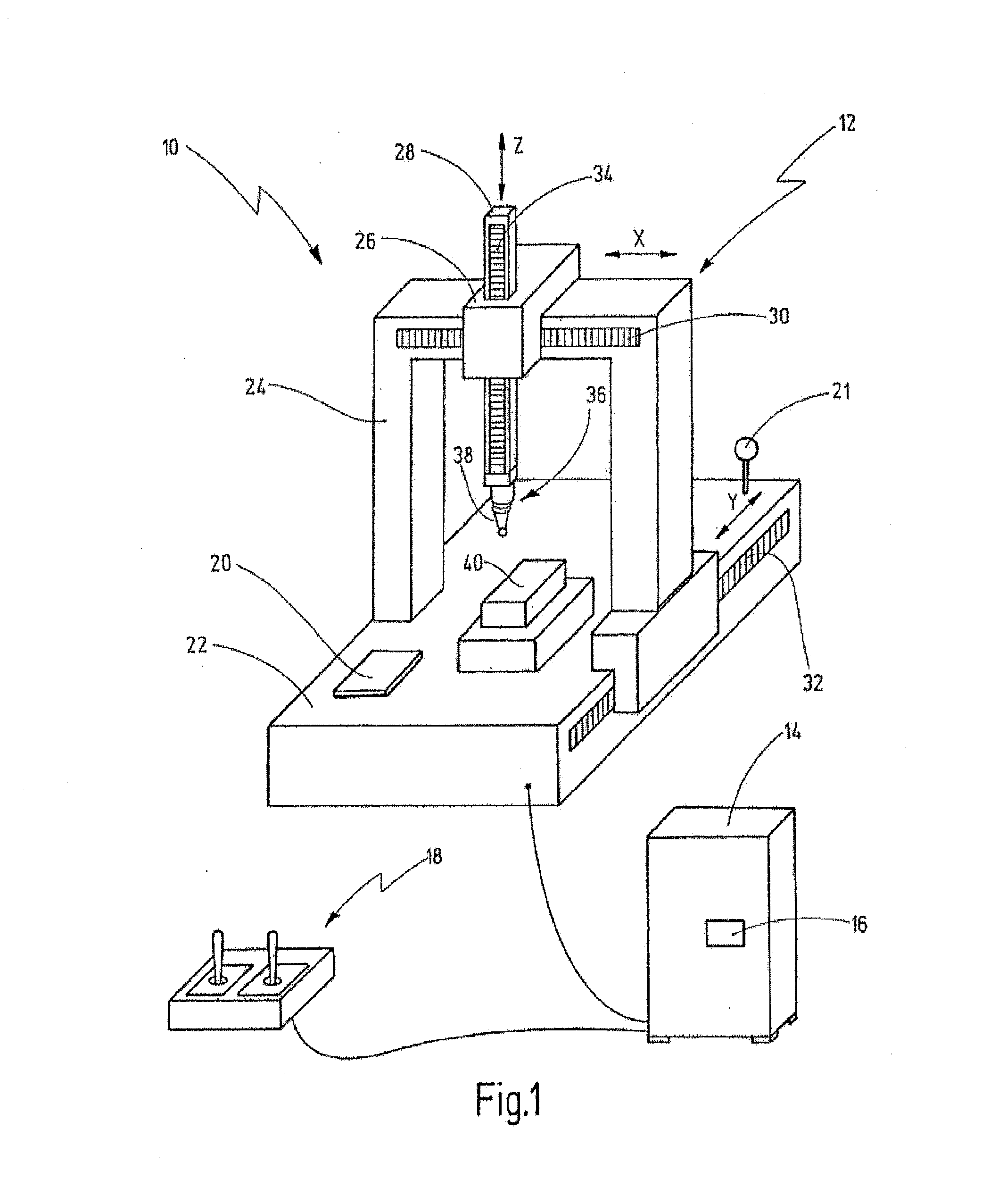
[0074]FIG. 1 shows a system 10 that can be used to carry out a method for collision detection or a method for correcting image data. The system 10 has a coordinate measuring machine 12 and a control unit 14 for controlling the coordinate measuring machine 12. The control unit 14 has an arithmetic logic unit 16, for example a computer.

[0075]The control unit 14 is illustrated purely schematically as a block; in principle, the control unit 14 can have all elements required for controlling the coordinate measuring machine 12, for example keyboards, monitors or a control console 18. Furthermore, the control unit 14 also comprises output means for outputting the data obtained by the coordinate measuring machine 12 in a suitable form, for example electronically or in paper form. Although the coordinate measuring machine 12 can also be operated manually by means of the control console 18, the control unit 14 is also capable of carrying out measurement and calibration processes in an automat...


PUM


Abstract

The present invention relates to a coordinate measuring machine having a sensor for measuring an object, and having a housing structure for holding and positioning the sensor, wherein a position change sensor is provided in order to detect a change in position of the sensor and of the housing structure. Further, the invention relates to a method for collision detection of a coordinate measuring machine. Last, the invention relates to a method for correcting data of a sensor, measuring in a contactless fashion, in particular an optical sensor, of a coordinate measuring machine. The method according to the second and the third aspects can be executed on a coordinate measuring machine according to the first aspect.

Description

CROSS-REFERENCE TO RELATED APPLICATIONS[0001]This is a continuation application of International patent application PCT / EP2010 / 064869, filed Oct. 6, 2010, which was published in German and claims the priority of German patent application DE 10 2009 049 534.7, filed Oct. 6, 2009. The entire contents of these priority applications are incorporated herein by reference.BACKGROUND OF THE INVENTION[0002]The present invention relates to a coordinate measuring machine having a sensor for measuring an object, and having a housing structure for holding and positioning the sensor.[0003]Further, the present invention relates to a method for collision detection of a coordinate measuring machine having a tactile sensor for measuring an object, and having a housing structure for holding and positioning the tactile sensor.[0004]Furthermore, the present invention relates to a method for correcting image data of a sensor, measuring in a contactless fashion, in particular an optical sensor, of a coord...

Claims


Application Information

Patent Timeline
IPC IPC(8): G01B7/012G01B11/03
CPCG01B21/047G01B21/045
Inventor ENGEL, THOMAS
Owner CARL ZEISS IND MESSTECHN GMBH
Learn More