Passive alternating current sensor

a passive alternating current and sensor technology, applied in the field of current sensors, can solve the problems of easy out of function and operation of current sensors, and achieve the effects of preventing the heat generated by the flexible structure layer, enhancing the sensitivity and facilitating the installation of the passive alternating current sensor

Inactive Publication Date: 2012-10-04
DELTA ELECTRONICS INC
View PDF7 Cites 11 Cited by
  • Summary
  • Abstract
  • Description
  • Claims
  • Application Information

AI Technical Summary

Benefits of technology

[0010]In view of the foregoing subject, an objective of the present invention is to provide a passive alternating current sensor that can perform desired sensing process without being applied by electricity. Besides, the structure layer thereof can resist the fatigue and aging problems, and can prevent from generating heat, which affects the sensing procedure, due to the configured coil with a lot of rounds.
[0019]As mentioned above, the passive alternating current sensor of the present invention allows the current-carrying conductor to be measured to generate a static magnetic force applied to the magnetic body as well as the flexibility of the suspended structure for enabling the oscillation motion of the magnetic body with respect to the coil, and then measures the inductance current on the coil. This is a non-contact current sensing method, so that it can prevent the affect of the system to be detected. Compared with the prior art, the present invention does not need external electricity for driving the passive alternating current sensor, which means the passive alternating current sensor can generate the necessary electricity for itself, and does not need to configure the coil with a lot of rounds for enhancing its sensitivity. Thus, the present invention can prevent the heat generated by the flexible structure layer caused by the power consumption of the current-carrying coil, which may further affect the operation in the sensing process. Besides, since the flexible structure layer is made of a single-crystal silicon material, the passive alternating current sensor of the present invention can resist the fatigue and aging problems after being used for a long term.
[0020]In addition, the present invention combines the piezoelectric element, magnetic body and flexible structure layer, which together form a piezoelectric energy harvester for generating energy to the signal transmitting unit, so that the entire passive alternating current sensor does not need the external power source but can individually operate to sense the current and output the detection result. Accordingly, the present can make the installation of the passive alternating current sensor more easily.
[0021]Otherwise, the piezoelectric element, the magnetic body, and the flexible structure layer may be applied to a second measuring circuit, so that the passive alternating current sensor can provide both the electromagnetic and piezoelectric current sensing mechanisms. Accordingly, the sensitivity of the passive alternating current sensor of the present invention can be enhanced, and the application range thereof can be further spread.

Problems solved by technology

Thus, the MEMS structure layer 13 must bear the most reciprocating force all the time, so that it is easily out of function due to fatigue and aging.
However, the power consumption of the coil 11 may cause the MEMS structure layer 13 to generate heat so as to increase the temperature and generate heat stress, which may affect the operation of the current sensor 1.

Method used


Image

  • Passive alternating current sensor
  • Passive alternating current sensor
  • Passive alternating current sensor

Examples


first embodiment

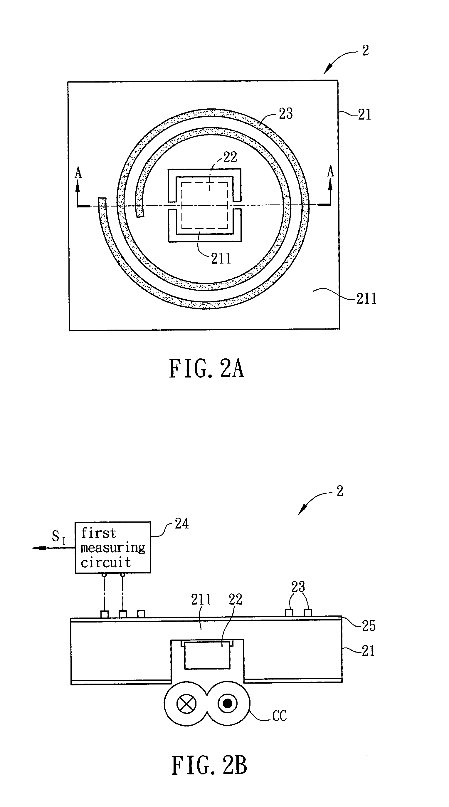
[0031]FIG. 2A is a top view showing a part of a passive alternating current sensor 2 according to the present invention, and FIG. 2B is a sectional view of the passive alternating current sensor 2 along the line A-A of FIG. 2A. Referring to FIGS. 2A and 2B, the passive alternating current sensor 2 is used for sensing the alternating current of a current-carrying conductor CC. The passive alternating current sensor 2 includes a substrate 21, a magnetic body 22, at least one coil 23 and a first measuring circuit 24.

[0032]The substrate 21 has a flexible structure layer 211. In this case, the substrate 21 is a single-crystal silicon substrate, and the flexible structure layer 211 is a suspended structure layer, which contains micro-suspended structures. In practice, the flexible structure layer 211 containing the micro-suspended structures can be manufactured by bulk micromachining the single-crystal silicon substrate according to the MEMS manufacturing processes. The suspended structur...

third embodiment

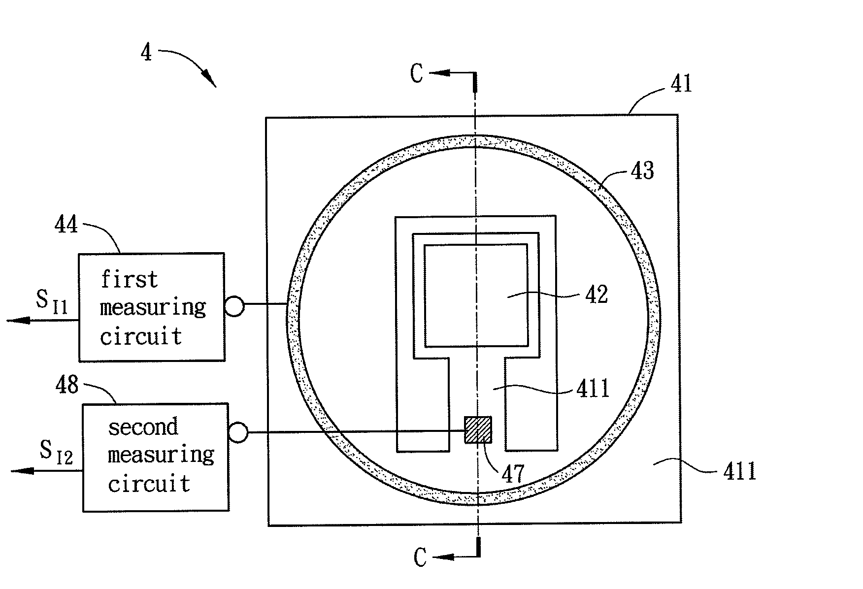
[0038]To be noted, except the above-mentioned piezoelectric energy harvester, the piezoelectric element 37, the magnetic body 32, and the flexible structure layer 311 may be applied to a second measuring circuit for enhancing the sensitivity of the passive alternating current sensor 3. FIG. 4A is a top view of a passive alternating current sensor 4 according to the present invention, and FIG. 4B is a sectional view of the passive alternating current sensor 4 along the line C-C of FIG. 4A. In this embodiment, the passive alternating current sensor 4 comprises a magnetic body 42 and a flexible structure layer 411, and a second measuring circuit 48 connects to a piezoelectric element 47. The operation of the passive alternating current sensor 4 will be described hereinafter. When the magnetic body 42 is subjected to the magnetic field generated by the current-carrying conductor CC so as to generate a magnetic force, which is applied to the flexible structure layer 411, the flexible str...


PUM


Abstract

A passive alternating current sensor for sensing a current-carrying conductor is disclosed. The passive alternating current sensor includes a substrate, a magnetic body, at least one coil and a first measuring circuit. The substrate has a flexible structure layer. The magnetic body is disposed correspondingly to the current-carrying conductor and located at one side of the substrate. The coil is disposed on the substrate and correspondingly winds around the magnetic body. The first measuring circuit is connected with the coil. When the magnetic body is subjected to the magnetic field generated by the current-carrying conductor and enabled a relative motion with the coil, the coil produces an induced electromotive force. The first measuring circuit measures the induced electromotive force and accordingly outputs a first induction signal.

Description

CROSS REFERENCE TO RELATED APPLICATIONS[0001]The non-provisional patent application claims priority to U.S. provisional patent application with Ser. No. 61 / 470,796 filed on Apr. 1, 2011. This and all other extrinsic materials discussed herein are incorporated by reference in their entirety.BACKGROUND OF THE INVENTION[0002]1. Field of Invention[0003]The present invention relates to a current sensor and, in particular, to a passive alternating current sensor.[0004]2. Related Art[0005]In industries, the current detection is usually applied to the applications of system over-current protection and current control, such as power decay detection, motor overload detection and protection, current mode control for power source, and control system diagnosis.[0006]The conventional current sensors include contact or non-contact sensing methods. The contact sensing method is to configure a sensing circuit for measuring the resistance, inductance, capacitance, or voltage between two ends of the t...

Claims


Application Information

Patent Timeline
Patent Type & Authority Applications(United States)
IPC IPC(8): H02N2/18G01R33/038
CPCG01R15/183
Inventor HSIEH, HSIEH-SHENCHUNG, TING-YICHANG, HENG-CHUNG
Owner DELTA ELECTRONICS INC
Why Eureka
Try Eureka