Electric motor control device

a technology of electric motors and control devices, which is applied in the direction of electric generator control, dynamo-electric converter control, dynamo-electric gear control, etc., can solve the problems of high power loss within the range in which armature current can be output, the value of d-axis current that may produce necessary power loss may not be determined appropriately, and the effect of suppressing the effect of high-order harmonic components

Inactive Publication Date: 2012-10-04
AISIN AW CO LTD
View PDF0 Cites 42 Cited by
  • Summary
  • Abstract
  • Description
  • Claims
  • Application Information

AI Technical Summary

Benefits of technology

[0018]When the current phase is shifted from an optimum phase, vibration components in the inductance of the armature coils are increased. The vibration components are high-order harmonic components in the current phase. When such harmonic components are produced in the inductance, the harmonic components affect current control and the voltage determined as a result of the current control, and finally affect output torque of the AC electric motor to produce torque ripples. Ripples are also produced in drive power and regenerative power. When high-loss control is executed, in particular, it is highly possible that the armature current is large, and thus it is preferable that the effect of the high-order harmonic components can be suppressed.

Problems solved by technology

However, Japanese Patent Application Publication No. 2003-134602 does not at all describe how to determine the value of the d-axis current with a magnitude determined in accordance with the amount of energy to be regenerated.
Therefore, the value of the d-axis current that may produce necessary power loss may not be determined appropriately, and necessary power loss may not be produce

Method used


Image

  • Electric motor control device
  • Electric motor control device
  • Electric motor control device

Examples


Embodiment Construction

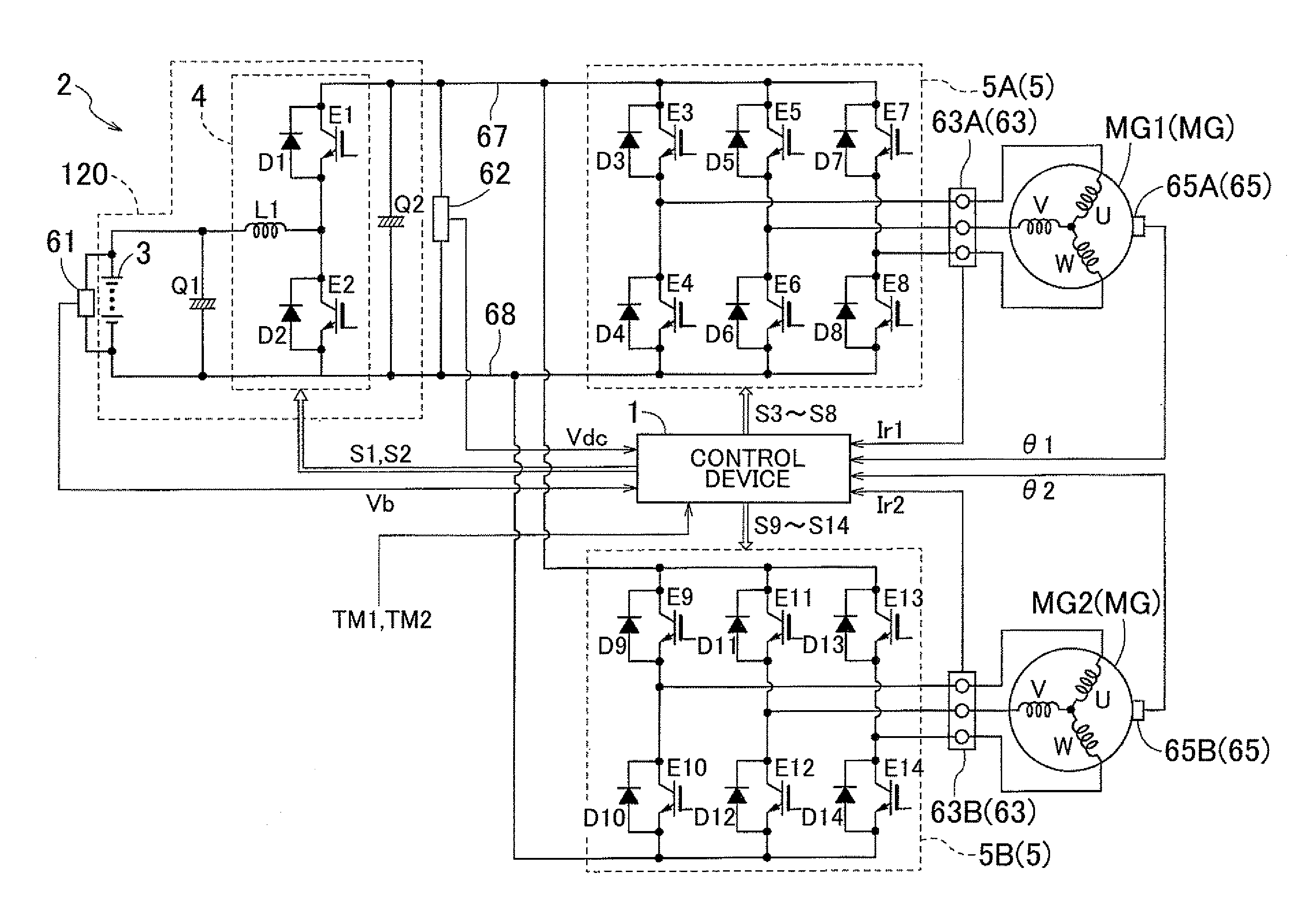
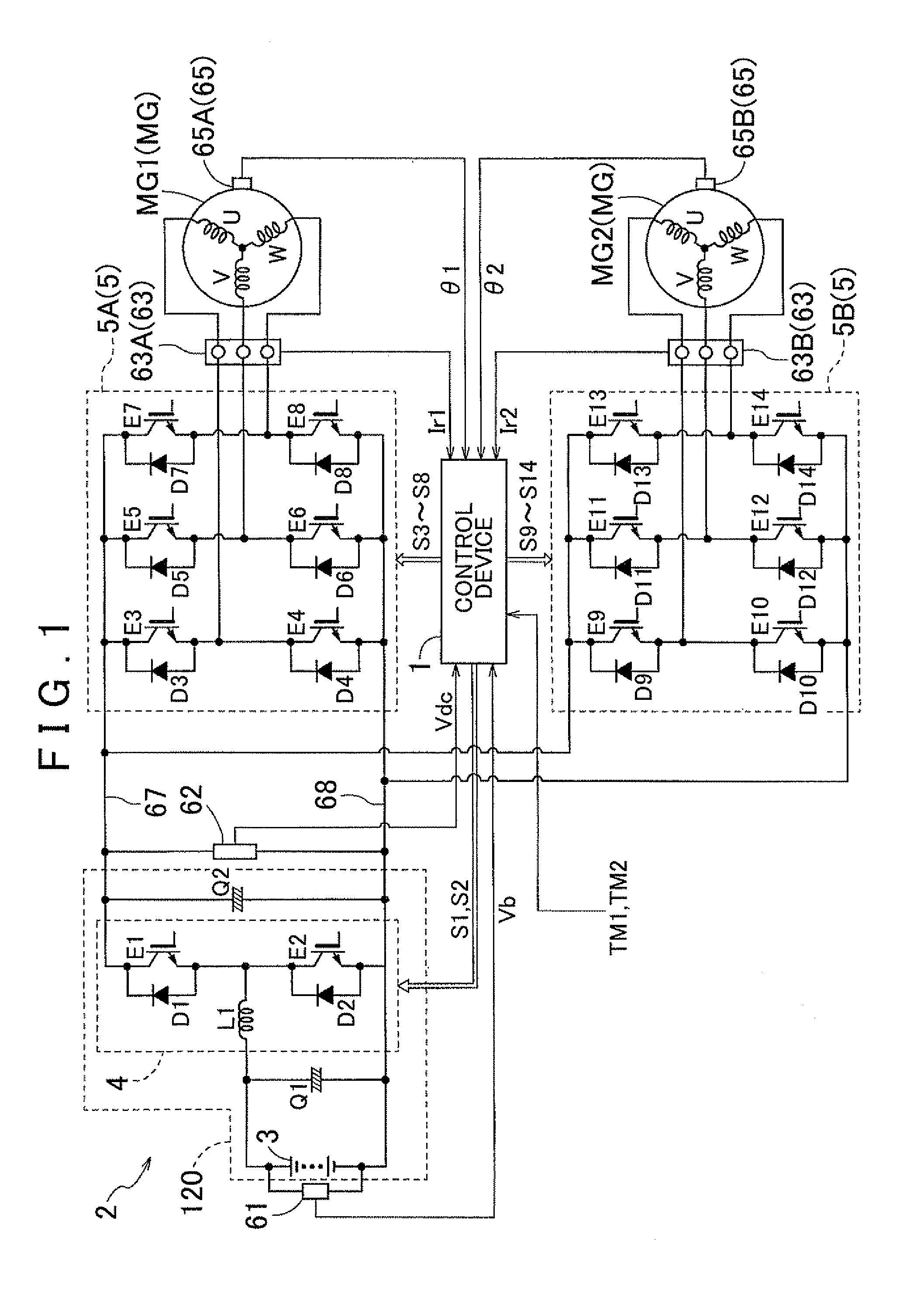
[0028]An embodiment of the present invention will be described with reference to the drawings using a case where the present invention is applied to a drive device for a hybrid vehicle of a so-called 2-motor split type as an example. The hybrid vehicle includes an internal combustion engine (not shown) and a pair of electric motors (AC electric motors) MG1 and MG2 each serving as a drive power source. The drive device for the hybrid vehicle also includes a differential gear device (not shown) for power distribution that distributes output of the internal combustion engine to the side of a first electric motor MG1 and the side of wheels and a second electric motor MG2. In the embodiment, an electric motor drive device 2 is formed as a device for driving the two electric motors MG1 and MG2. Here, each of the first electric motor MG1 and the second electric motor MG2 is an AC electric motor that operates on 3-phase AC, and an interior permanent magnet synchronous motor (IPMSM). The ele...


PUM


Abstract

An electric motor control device includes a mode in which an inverter is controlled by a current phase of an armature current in a 2-axis orthogonal vector space, a vector being obtained by synthesizing a field and a drive current along two axes defining the vector space; a high-loss control section that, when extra power results from charging a power storage device, varies the field current in accordance with the extra power to increase the armature current while maintaining torque of an AC electric motor; and the high-loss control section varies the field current to one of a field weakening and a field intensifying side of the electric motor, which results in the higher power loss within a range in which the armature current can be output in the vector space and which is determined based on the DC power source voltage and a rotational speed of the electric motor.

Description

INCORPORATION BY REFERENCE[0001]The disclosure of Japanese Patent Application No. 2011-076561 filed on Mar. 30, 2011 including the specification, drawings and abstract is incorporated herein by reference in its entirety.BACKGROUND OF THE INVENTION[0002]The present invention relates to an electric motor control device that controls an electric motor drive device including an inverter that is interposed between a DC power source including a power storage device and an AC electric motor and performs power conversion between DC power of the DC power source and 3-phase AC power.DESCRIPTION OF THE RELATED ART[0003]Automobiles that impose a reduced load on the environment compared to those according to the related art are proposed in order to reduce the load on the environment due to consumption of fossil fuel. Examples of such automobiles include electric vehicles driven by an AC electric motor and hybrid vehicles driven by an internal combustion engine and an AC electric motor. In the el...

Claims


Application Information

Patent Timeline
IPC IPC(8): H02P21/00B60L7/22B60L50/16H02P21/12H02P21/22H02P27/04H02P27/08
CPCB60L7/10H02P29/0038H02P21/0089H02P21/06Y02T10/643H02P29/0044B60L15/025B60L2220/42B60L2240/423B60L2240/527B60L58/15H02P29/50H02P29/60Y02T10/64Y02T10/70
Inventor SAHA, SUBRATAIWATSUKI, KEN
Owner AISIN AW CO LTD
Why Eureka
Try Eureka