Method of manufacturing a glass substrate for a magnetic disk and method of manufacturing a magnetic disk

a glass substrate and magnetic disk technology, applied in the direction of cleaning using liquids, lapping machines, other chemical processes, etc., can solve the problems of increasing the possibility of collision with the magnetic head, increasing the roughness, and degrading the end face shape, so as to reduce the roughness of the main surface of the substrate and reduce the cost. , the effect of less surface defects

Active Publication Date: 2012-10-04
HOYA CORP
View PDF12 Cites 7 Cited by
  • Summary
  • Abstract
  • Description
  • Claims
  • Application Information

AI Technical Summary

Benefits of technology

[0044]According to this invention, it is possible to manufacture, at a low cost, a high-quality magnetic disk glass substrate with less roughness of a substrate main surface and with less surface defects due to adhesion of foreign matter or the like than a conventional product. The magnetic disk glass substrate obtained by this invention can be suitably used particularly as a next-generati

Problems solved by technology

Under these circumstances, if a convex surface defect due to adhesion of extremely small foreign matter (for example, having a size of about 10 to 40 nm at minimum) or the like, which did not arise as a problem conventionally, is present on a substrate surface while the average roughness of the substrate surface is extremely small, it directly becomes a convex defect even on the medium surface, and therefore, the possibility of collision with the magnetic head increases.
According to a study by the present inventors, by controlling the particle size of t

Method used


Image

  • Method of manufacturing a glass substrate for a magnetic disk and method of manufacturing a magnetic disk
  • Method of manufacturing a glass substrate for a magnetic disk and method of manufacturing a magnetic disk
  • Method of manufacturing a glass substrate for a magnetic disk and method of manufacturing a magnetic disk

Examples


example 1

[0095]A magnetic disk glass substrate of this Example was manufactured through (1) Rough Lapping Process (Rough Grinding Process), (2) Shaping Process, (3) Precision Lapping Process (Precision Grinding Process), (4) End Face Polishing Process, (5) Main Surface First Polishing Process, (6) Chemical Strengthening Process, and (7) Main Surface Second Polishing Process, which will be described hereinbelow.

[0096](1) Rough Lapping Process

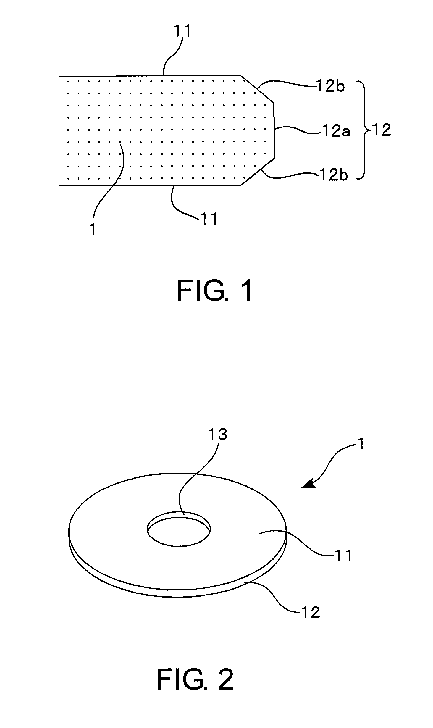
[0097]First, a disk-shaped glass substrate made of an aluminosilicate glass and having a diameter of 66 mm and a thickness of 1.0 mm was obtained from a molten glass by direct pressing using upper, lower, and drum molds. Alternatively, a plate glass may be manufactured by a downdraw method or a float method and then cut into a disk-shaped glass substrate with a predetermined size. As the aluminosilicate glass, use was made of a glass for chemical strengthening containing 58 wt % to 75 wt % SiO2, 5% W % to 23 wt % Al2O3, 3 wt % to 10 wt % Li2O, and 4 wt % ...

example 2

[0118]The glass substrate was manufactured in the manner similar to Example 1 except that colloidal silica abrasive particles having an average particle size of 10 nm were used in the main surface second polishing process in Example 1.

example 3

[0119]The glass substrate was manufactured in the manner similar to Example 1 except that colloidal silica abrasive particles having an average particle size of 40 nm were used in the main surface second polishing process in Example 1.


PUM

PropertyMeasurementUnit
Fractionaaaaaaaaaa
Particle sizeaaaaaaaaaa
Concentrationaaaaaaaaaa

Abstract

In a magnetic disk glass substrate manufacturing method, a main surface of a glass substrate is polished using a polishing liquid containing colloidal silica abrasive particles as polishing abrasive particles and a surface plate with a polishing pad, then the glass substrate is brought into contact with a liquid containing a coagulant so that the colloidal silica abrasive particles are coagulated, and then the colloidal silica abrasive particles coagulated are removed.

Description

[0001]This application is based upon and claims the benefit of priority from Japanese patent application No. 2011-080153, filed on Mar. 31, 2011, the disclosure of which is incorporated herein in its entirety by reference.TECHNICAL FIELD[0002]This invention relates to a method of manufacturing a glass substrate for a magnetic disk adapted to be mounted in a magnetic disk device such as a hard disk drive (HDD) and further relates to a method of manufacturing the magnetic disk. Hereinafter, a glass substrate for a magnetic disk may also be referred to as a magnetic disk glass substrate.BACKGROUND ART[0003]As an information recording medium adapted to be mounted in a magnetic disk device such as a hard disk drive (HDD), there is a magnetic disk. The magnetic disk is produced by forming a thin film such as a magnetic layer on a substrate and, conventionally, an aluminum substrate has been used as such a substrate. Recently, however, in response to the pursuit of higher recording density...

Claims


Application Information

Patent Timeline
IPC IPC(8): B24B1/00G11B5/84
CPCB08B3/04B08B3/12C09G1/02B24B37/08G11B5/8404B24B37/044C09K3/1409
Inventor SAKAI, HIDEOSUZUKI, YOSUKETAWARA, YOSHIHIRO
Owner HOYA CORP
Why Eureka
Try Eureka