[0013]Using this construction and operation, it is therefore possible to
route new
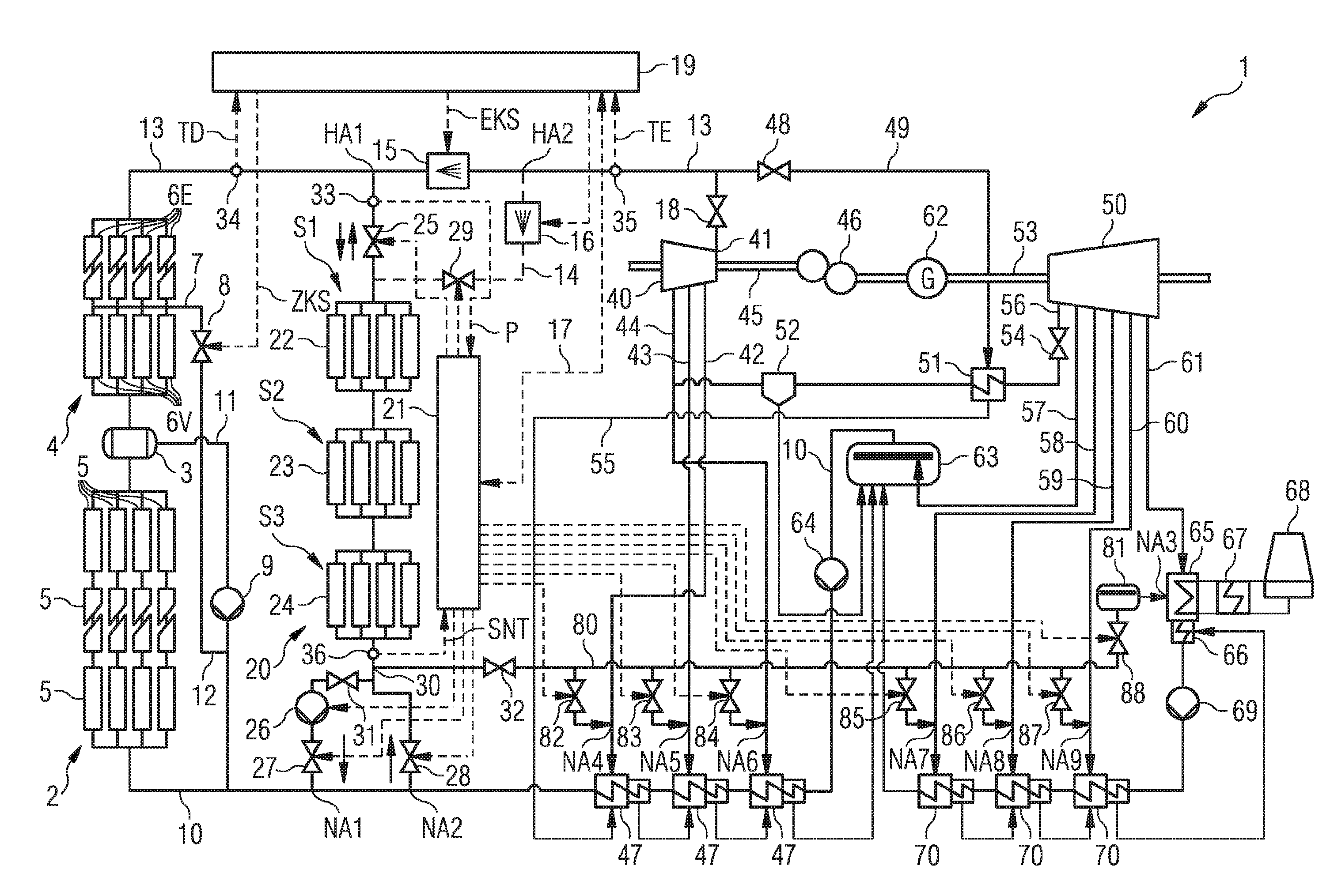
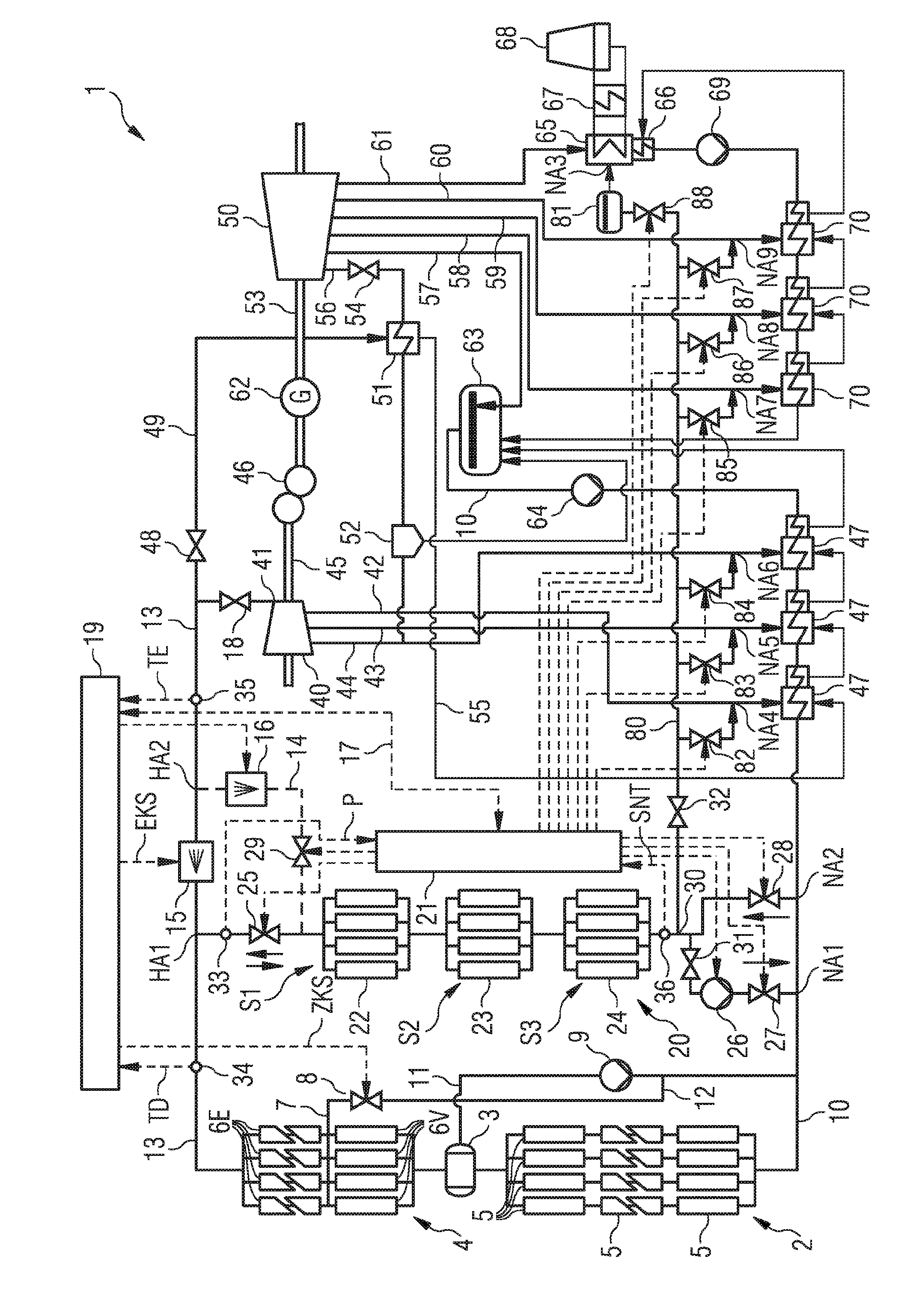
superheated steam continuously into the intermediate storage at the high-temperature storage connecting point during the storage mode. Since the heat store is not normally able to absorb
thermal energy at a
constant rate over the whole duration of the storage mode, the
temperature and pressure conditions can change at the end of the heat store on the low-temperature side as a function of the duration of the storage mode, i.e. after energy has already been absorbed by the heat store, and water, steam or a water / steam mixture can occur there depending on the conditions at the time. According to the invention, the intermediate storage is therefore also connected at a low-temperature storage connecting point (preferably directly but also indirectly if applicable, i.e. via further components) to a condenser and / or a relaxation device of the solar thermal power plant. The relaxation device can be e.g. a relaxation container or similar, in which the pressurized steam or the water / steam mixture is relaxed atmospherically, for example. According to the invention, it is also possible in the context of a suitable
layout to use a supply water container as a relaxation device for carrying away the medium at the end of the intermediate storage on the low-temperature side in this case. In particular, a relaxation container can preferably be connected between the outlet on the low-temperature side of the intermediate storage and the condenser. This is particularly advantageous if it is stipulated by the manufacturer of the condenser
system that only
liquid medium should enter the condenser from such a secondary line. The supply line to a condenser or to a relaxation device has the
advantage that, irrespective of the
temperature and pressure ratios and irrespective of the state of aggregation of the medium (water and / or steam) at the outlet of the intermediate storage, the medium can be carried away and supplied back to the water / steam circuit of the solar thermal power plant. Very high thermal charging of the heat store is therefore possible. This means that the intermediate storage can be brought to a higher temperature level overall than in the case of a design in which e.g. only one storage operation is possible, as long as the
absorption capacity of the heat store is sufficient to convert the steam completely into the
liquid phase and add the
condensed water to the supply water. Conversely, during the extraction mode a greater quantity of energy or thermal energy can then be extracted from the intermediate storage at a comparatively higher temperature level, such that the live steam temperature can also be better utilized during full-load operation of the
solar field.
[0023]If the high-temperature storage connecting point at which the steam is routed into the intermediate storage lies upstream (in the direction of flow) of the steam cooling device in which the temperature of the live steam is regulated down to the value required by the turbine, the steam that is used to charge the storage is extracted from the main steam circuit at the point which has the highest steam temperature. It is therefore also possible for steam that has a higher temperature than the required live steam temperature to be fed back from the intermediate storage during the extraction mode, such that the storage can be used not only to provide additional steam, but also to counteract a
temperature drop in the steam coming from the solar collector steam superheater unit, i.e. to compensate for the
temperature drop by introducing a hotter steam. By virtue of the additional admixture of steam of a higher temperature in the inventive manner, it is therefore possible (even if a final-stage steam cooling device is fully deactivated, i.e. the injection fixture is closed) to maintain the live steam temperature at a constant level within specified limits, even if the steam delivered by the solar collector steam superheater unit is lower than the live steam temperature. This means that the live steam temperature for the turbine can more easily be kept within predefined limits even in the case of a partial output of the solar collector steam generator unit and / or of the solar collector steam superheater unit. The availability and operational flexibility of the entire solar thermal power plant is therefore increased.
[0025]The arrangement has a further
advantage in that, in the event of a short-term demand for output reserves (so-called “seconds reserve”), the thermal energy stored in the long-term storage can be used for additional steam production even if there is no drop in the temperature of the steam coming from the solar collector steam superheater unit, and it is merely necessary to increase the steam quantity for the purpose of increased output. The additionally generated steam can then be admixed with the main steam
stream in the steam conduit
system again before the final-stage steam cooling device, and brought to the live steam temperature in the cooling device. As a result of the advantageous
coupling of the intermediate storage to the steam conduit system before the final-stage steam cooling device, it is easily possible to ensure a constant live steam temperature during the provision of seconds reserve.
[0029]During the extraction mode, the intermediate storage is likewise connected to the steam conduit system between the solar collector steam superheater unit and the steam turbine by means of opening a valve, the opening of the valve however being preferably regulated here to give a constant temperature in the steam conduit system at the high-temperature storage connecting point. If the feeding in of the steam from the intermediate storage takes place at the first high-temperature storage connecting point (i.e. ahead of the final-stage steam cooling device), at which the steam is also routed from the steam conduit system into the storage, it is thus possible to ensure that the temperature is already maintained at a value that is as constant as possible ahead of the last steam cooling device, such that no great regulation variations occur in the context of the
temperature control using the final-stage steam cooling device.

