Control method and apparatus

a control method and control apparatus technology, applied in the direction of electric supply techniques, electrochemical generators, separation processes, etc., can solve the problems of compound membrane elements and specifically, elements employed in such elements, degrade or age over time, and the voltage will steadily increas

Active Publication Date: 2012-10-11
PRAXAIR TECH INC
View PDF8 Cites 1 Cited by
  • Summary
  • Abstract
  • Description
  • Claims
  • Application Information

AI Technical Summary

Benefits of technology

[0007]In one aspect, the present invention provides a method for controlling application of electrical power in an electrically driven oxygen separation device. In accordance with the method, part of the electrical power is applied in at least one separation zone of the electrically driven oxygen separation device in which an electrical potential difference is applied to anode and cath...

Problems solved by technology

The composite membrane elements and specifically, the elements employed in such elements, however, degrade or age over time principally due to closure of the pores, evaporation of metallic elements such as silver, silver migration from the cathode to the electrolyte, reactions occurring between the electrodes and the electrolyte and delamination of the current collector.
However, if a constant current is applied, the voltage will steadily increase until failure of the membrane elements occurs.
This failure will occur over a known time period and consequently, renewal of the device is scheduled in a conservative fashion to allow the composite membrane elements to be replaced in advanc...

Method used


Image

  • Control method and apparatus
  • Control method and apparatus
  • Control method and apparatus

Examples


Embodiment Construction

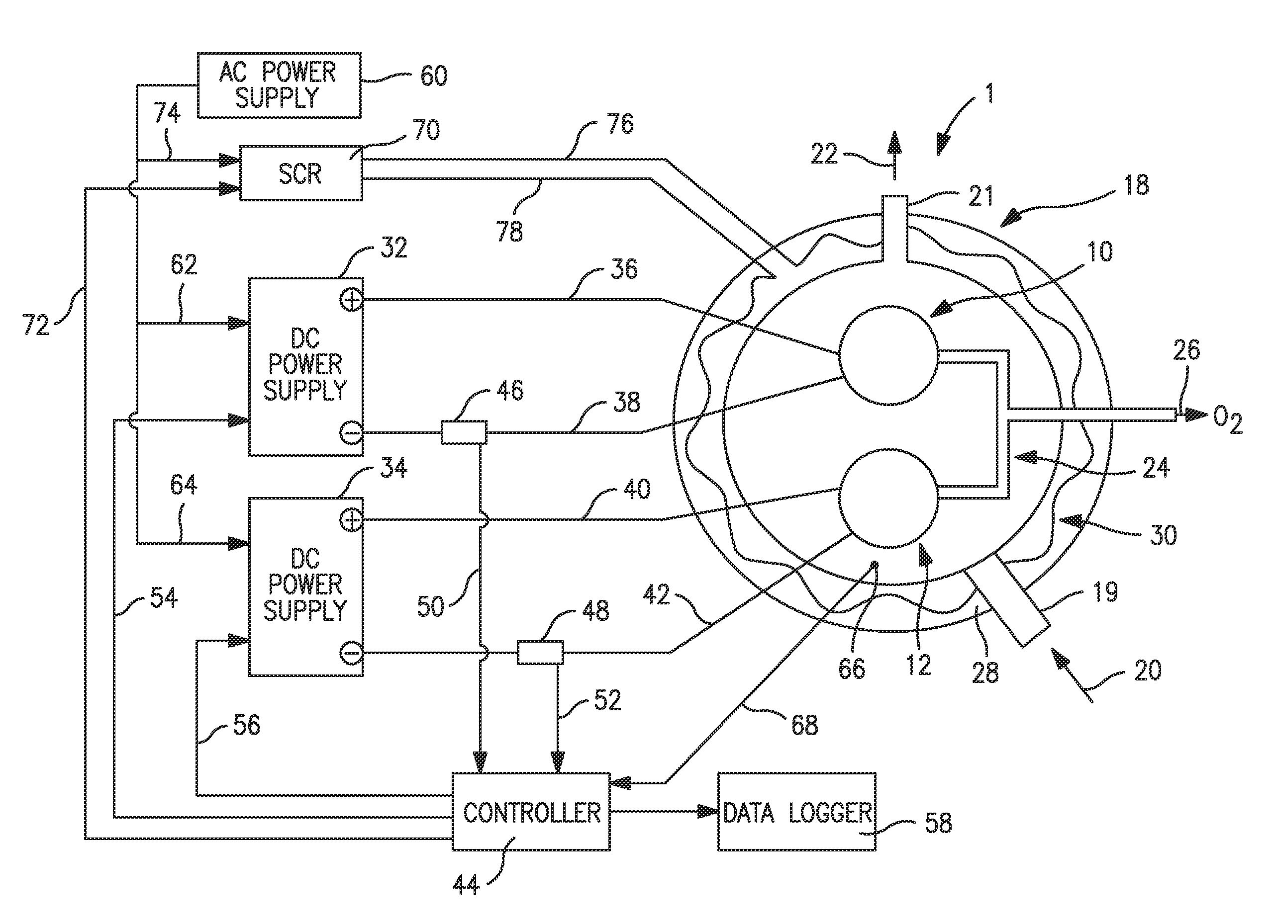
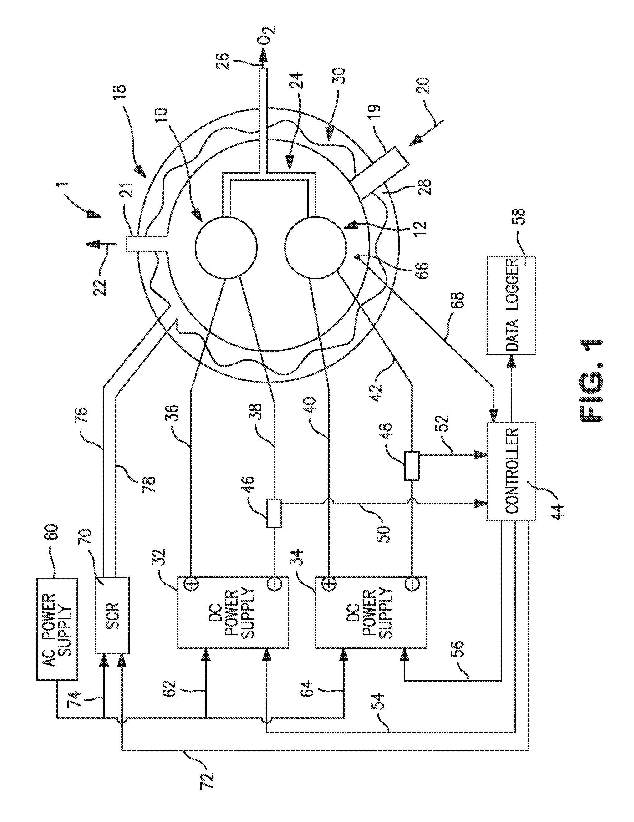
[0020]With reference to FIG. 1, an electrically driven oxygen separation device 1 incorporating an electrical power supply in accordance with the present invention is illustrated. Electrically driven oxygen separation device 1 is illustrating as having a first composite membrane element 10 and a second composite membrane element 12 housed within an electrically heated enclosure 18.

[0021]The electrical power supply to the electrically driven oxygen separation device separation device 1 is illustrated as incorporating two separation zones. One of the two separation zones consists of a DC power supply 32, the first composite membrane element 10, an electrical current sensor 46 and the other of the two separation zones consists of a DC Power Supply 34, the second composite membrane element 12 and a second current sensor 48. Current sensor 46 and 48 could be a current sense resistor or any other current measurement device. Also the current measurement device could be integrated into powe...


PUM

PropertyMeasurementUnit
Temperatureaaaaaaaaaa
Poweraaaaaaaaaa
Electrical resistanceaaaaaaaaaa

Abstract

A method and apparatus for controlling the electrical power applied to an electrically driven oxygen separation device having one or more composite membrane elements to separate oxygen from an oxygen containing feed. The composite membrane elements have a resistance increasing during the operation thereof that would act to reduce oxygen output if applied voltage were held constant. In order to increase the time interval for renewing the composite membrane elements, the electrical potential difference is controlled such that the electric current drawn by the elements remains at a substantially constant level by increasing the electrical potential difference as the resistance increases until a predetermined voltage level is reached. Once this level is obtained, the electrical potential difference is maintained at a constant level and the electric current being drawn and the oxygen output is allowed to decay to a predetermined low level after which the element or elements are replaced.

Description

FIELD OF THE INVENTION[0001]The present invention relates to a method and apparatus for controlling the electrical power applied to an electrically driven oxygen separation device employing one or more composite membrane elements having anode and cathode electrodes and an electrolyte situated between the anode and cathode electrodes to separate oxygen from an oxygen containing feed stream. More particularly, the present invention relates to such a method and apparatus in which a potential difference applied to the membrane elements is increased over time to maintain electric current drawn by the composite membrane element constant during the increase and is thereafter, held at a constant level.BACKGROUND OF THE INVENTION[0002]Electrically driven oxygen separation devices employ one or more composite membrane elements that have cathode and anode electrodes situated on opposite sides of an electrolyte to apply an electric potential difference to the electrolyte. The electrolyte is a c...

Claims


Application Information

Patent Timeline
IPC IPC(8): B03C3/34
CPCB01D53/22B01D53/326Y02E60/366B01D2257/102C01B13/0251B01D2256/12Y02E60/36
Inventor COLLINS, MICHAEL J.SUGGS, DAVID F.SWAMI, SADASHIV M.KELLY, RICHARD M.
Owner PRAXAIR TECH INC
Why Eureka
Try Eureka