Solid oxide fuel cell device

a fuel cell and solid oxide technology, applied in the direction of fuel cells, fuel cell grouping, solid electrolyte fuel cells, etc., can solve the problems of difficulty in enhancing the durability of the fuel cell, risk of explosion of mixed fuel gas, and inconvenient portability, so as to continue to generate electric power stably and convenient portability

Inactive Publication Date: 2006-09-14
SHINKO ELECTRIC IND CO LTD
View PDF2 Cites 1 Cited by
  • Summary
  • Abstract
  • Description
  • Claims
  • Application Information

AI Technical Summary

Benefits of technology

[0030] As described above, the solid oxide fuel cell device according to the invention employs a solid oxide fuel cell including a planar solid oxide substrate, a cathode electrode layer, and an anode electrode layer; and is configured so as to generate electric power on the basis of the anode electrode layer being supplied with an oxidation fuel component of fuel produced on the catalytically-oxidizing member; and the cathode electrode layer being supplied with air. Therefore, heat can be produced by flameless combustion based on catalytic oxidation of the fuel without a flame produced by combustion of the fuel; and the heat can maintain the solid oxide fuel cell at an operating temperature. In addition, partial oxidation fuel components produced by flameless combustion based on the catalytic oxidation of the fuel can be used as fuel of the fuel cell device.
[0031] Hence, when the solid oxide fuel cell is incorporated in a heating appliance whose heat source is flameless combustion based on catalytic oxidation, the appliance can be configured small, lightweight, and compact. In addition, the appliance is conveniently portable, and can continue to generate electric power stably even while the appliance is carried on the road or while on the move.

Problems solved by technology

As a result, a potential difference arises between the cathode layer and the anode layer.
Furthermore, since the fuel cell device is to be exposed to an oxidizing atmosphere and to a reducing atmosphere at high temperatures, enhancement of durability of the fuel cell has encountered difficulty.
However, in view that even the single-chamber fuel cell device must be operated at high temperatures of approximately 1,000° C., there arises a risk of explosion of the mixed fuel gas.
Here, if the oxygen concentration is reduced to a level lower than the ignitability limit in an attempt to avoid the risk, there arises the problem that carbonization of the fuel, such as methane, progresses and the cell exhibits degraded performance.
However, the single-chamber fuel cell device inevitably employs a hermetically-sealed structure.
As a result, the single-chamber fuel cell device employing the planar solid oxide fuel cells has a large-scale configuration, thereby posing a problem of being costly.
Accordingly, this type of fuel cell device requires a long time until power generation is started, and requires a lot of labor in operation.
However, in this type of fuel cell device, since the anode layer is formed on the outer surface of the tubular solid oxide substrate, radical components produced by means of the flame are not primarily supplied to a lower half of the anode layer.
Therefore, electrical generation efficiency has been low.
Furthermore, since the solid oxide fuel cell is heated directly by a flame and unevenly, there arises a problem that cracks are easily produced by rapid temperature changes.
However, since the diffusion flame is unstable, and is likely to incur degradation of the function of the anode layer due to production of soot, the premixed flame is more preferable.
As described above, a proposed electric power generation system of chamber type requires an electric furnace for raising the temperature of a solid oxide fuel cell to an operating temperature, a supply unit for supplying a fuel gas, and oxygen or air, and the like; hence, the system itself becomes complicated and voluminous.
Accordingly, the chamber-type system cannot be carried by a person as an electric power generation system.
However, since utilizing a flame is required for providing high temperature enough for the solid oxide fuel cell to generate electric power, the power generation system itself encounters difficulty in practical usage.
That is, because of the flame being not stabilized during the system being carried outside or being used under mobile condition, which ends up an unstable operation of the electric power generation.

Method used


Image

  • Solid oxide fuel cell device
  • Solid oxide fuel cell device
  • Solid oxide fuel cell device

Examples


example

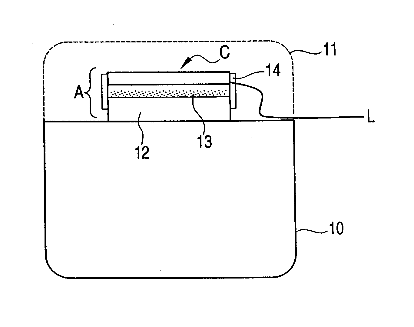
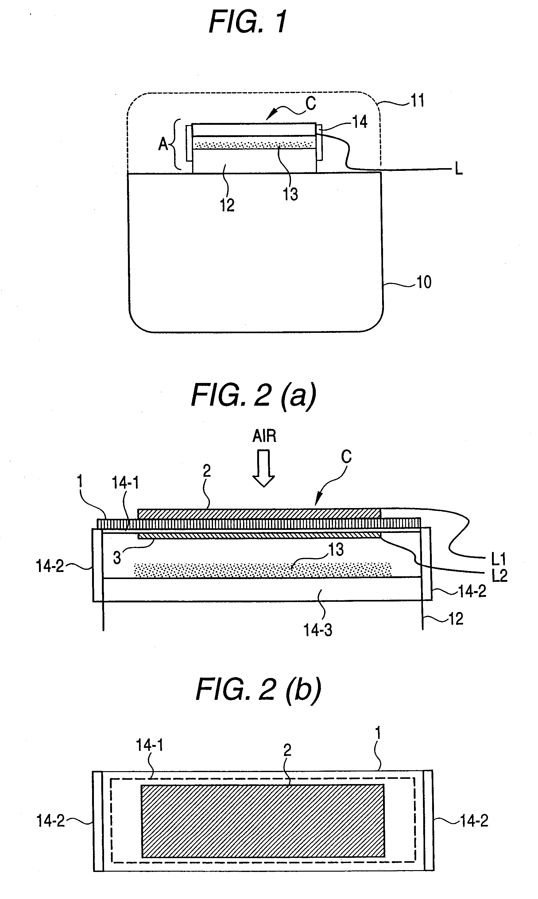
[0071]FIG. 1 illustrates an example of a direct-flame-type solid oxide fuel cell device which can supply fuel to a solid oxide fuel cell, and, in addition, which utilizes a catalytically-oxidizing member as a heat source for maintaining its operating temperature. The example illustrated in FIG. 1 utilizes a catalytically-oxidizing member provided in a platinum pocket warmer, which is a typical example of a heating appliance.

[0072] Generally, a portable-type platinum pocket warmer comprises a fuel storage container 10; an open fire recess A at an upper portion of the fuel storage container 10; a fuel supply port 12 through which fuel can be supplied from the fuel storage container 10; and a catalytically-oxidizing member 13 for catalyzing oxidation of the thus-supply fuel. The fuel supply port 12 and the catalytically-oxidizing member 13 are disposed in the open fire recess A. A protective cover 11 for covering the open fire recess A is attached after ignition of the fire, for ensur...


PUM

PropertyMeasurementUnit
thicknessaaaaaaaaaa
operating temperatureaaaaaaaaaa
temperaturesaaaaaaaaaa

Abstract

A solid oxide fuel cell C including a solid oxide fuel cell having a planar solid oxide substrate, a cathode electrode layer formed on one surface of the substrate, and an anode electrode layer formed on a surface opposite the one surface, is disposed so that the anode electrode layer opposes a catalytically-oxidizing member 13 of a heating appliance. Fuel supplied from a fuel storage container 10 is subjected to flameless combustion in the catalytically-oxidizing member by catalytic oxidation. The heat is conducted to the fuel cell C from the catalytically-oxidizing member, thereby maintaining the fuel cell at its operating temperature. Simultaneously, produced oxidation fuel components of the fuel are supplied to the anode electrode layer; and air is supplied to the cathode electrode layer. Hence, the fuel cell generates electric power.

Description

[0001] This application claims foreign priority based on Japanese Patent application No. 2005-69373, filed Mar. 11, 2005, the contents of which is incorporated herein by reference in its entirety. BACKGROUND OF THE INVENTION [0002] 1. Field of the Invention [0003] The present invention relates to a solid oxide fuel cell device. More particularly, the invention relates to a solid oxide fuel cell device which has a solid oxide fuel cell aiming at miniaturization and reduction in profile by employment of a simple structure which does not require sealing, and in which a cathode electrode layer (hereinafter called a “cathode layer”) and an anode electrode layer (hereinafter called an “anode layer”) are formed on a solid oxide substrate; which can generate electric power through utilization of flameless combustion based on catalytic oxidation of fuel, and which is convenient in handling, including carriage on the road and transport. [0004] 2.Description of the Related Art [0005] Conventio...

Claims


Application Information

Patent Timeline
Patent Type & Authority Applications(United States)
IPC IPC(8): H01M8/04H01M8/12
CPCH01M8/0637H01M8/1213H01M8/1233H01M2008/1293Y02E60/521Y02E60/525Y02E60/50
Inventor SUGANUMA, SHIGEAKITOKUTAKE, YASUEHORIUCHI, MICHIOWATANABE, MISA
Owner SHINKO ELECTRIC IND CO LTD
Why Eureka
Try Eureka