Photovoltaic modules for use in vehicle roofs, and/or methods of making the same

a technology for photovoltaic modules and vehicle roofs, applied in the direction of pv power plants, energy harvesting concepts, manufacturing tools, etc., can solve the problems of increasing affecting the performance of the vehicle, and the conventional approach to attaching pv devices to the sunroof may be problematic, so as to increase the cost and complexity of manufacturing, and the overall manufacturing process is more complex and complex. , the effect of increasing the number of assembly steps

Inactive Publication Date: 2012-10-18
GUARDIAN GLASS LLC
View PDF1 Cites 13 Cited by
  • Summary
  • Abstract
  • Description
  • Claims
  • Application Information

AI Technical Summary

Benefits of technology

[0010]Car manufactures may be able to compensate for this problem by designing car roofs to accommodate sunroofs with PV devices. However, this solution may create more problems. For example, this additional modification to the body of the car may increase the cost and complexity of manufacturing. The additional body modification may add to the at least two body structures already being produced for the car (e.g., one with a sunroof and one without). The additional thickness of the PV device also may further reduce the already reduced headroom provided in the passenger compartment of the car.
[0011]In addition, because the PV device may come from a supplier other than a normal sunroof supplier, the addition of the PV device may add more assembly steps and more complexity to the overall manufacturing process. Instead of just installing a sunroof during assembly, a car manufacturer may instead have to install a sunroof and then install the PV device. It will be appreciated that this convention PV installation may require a retooling of a production line.

Problems solved by technology

These structural changes to the car may sometimes increase both the cost and complexity of manufacturing.
However, this conventional approach for attaching PV devices to sunroofs may be problematic, e.g., because of the difficulties involved in adding to a sunroof a component that does not necessarily “fit,” forming any necessary or desirable electrical connections, matching the size and / or shape of the PV module to the sunroof and / or rooftop, maintaining the desirable structural integrity of the rooftop, etc.
This increased weight from the PV device attached to the sunroof may adversely affect the performance of the vehicle.
Further, the additional weight at such a high point in the car may increase the overall center of gravity of the car.
This may in turn lead to safety problems (e.g., a higher risk of turn over).
Furthermore, as alluded to above, integrating the newly installed PV device into the structure of the car may require modification of the body of the car because it may not “fit” without such modifications.
However, the addition of a PV device with its additional thickness may preclude the modified sunroof from retracting into the body of the roof.
However, this solution may create more problems.
For example, this additional modification to the body of the car may increase the cost and complexity of manufacturing.
The additional thickness of the PV device also may further reduce the already reduced headroom provided in the passenger compartment of the car.
In addition, because the PV device may come from a supplier other than a normal sunroof supplier, the addition of the PV device may add more assembly steps and more complexity to the overall manufacturing process.
The aftermarket installation of a PV device may also present additional problems or complications.
For already manufactured cars, the addition of a PV device (with its corresponding thickness) to the sunroof may require expensive after market customization including a re-structuring of the roof of the car.

Method used


Image

  • Photovoltaic modules for use in vehicle roofs, and/or methods of making the same
  • Photovoltaic modules for use in vehicle roofs, and/or methods of making the same
  • Photovoltaic modules for use in vehicle roofs, and/or methods of making the same

Examples


Embodiment Construction

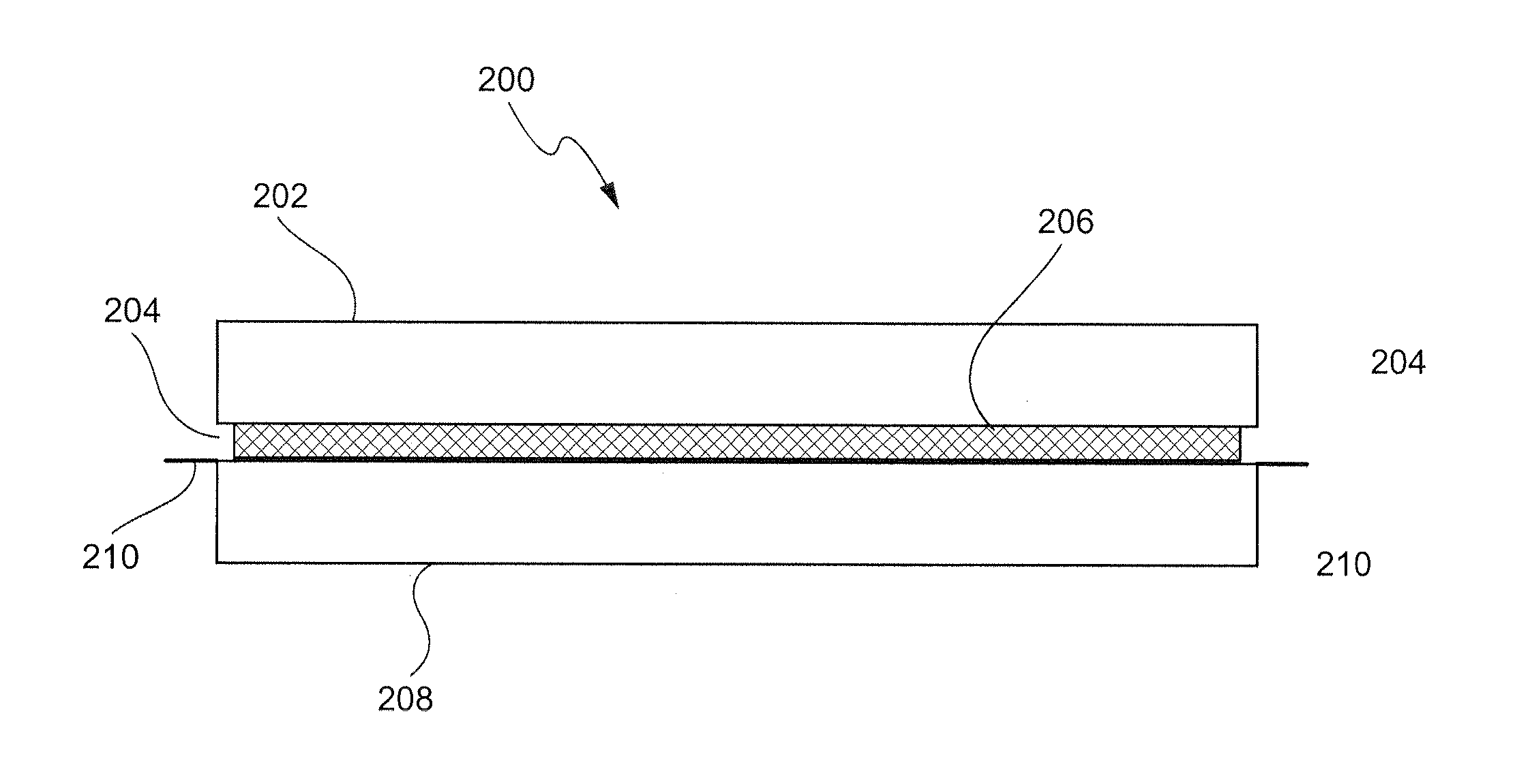
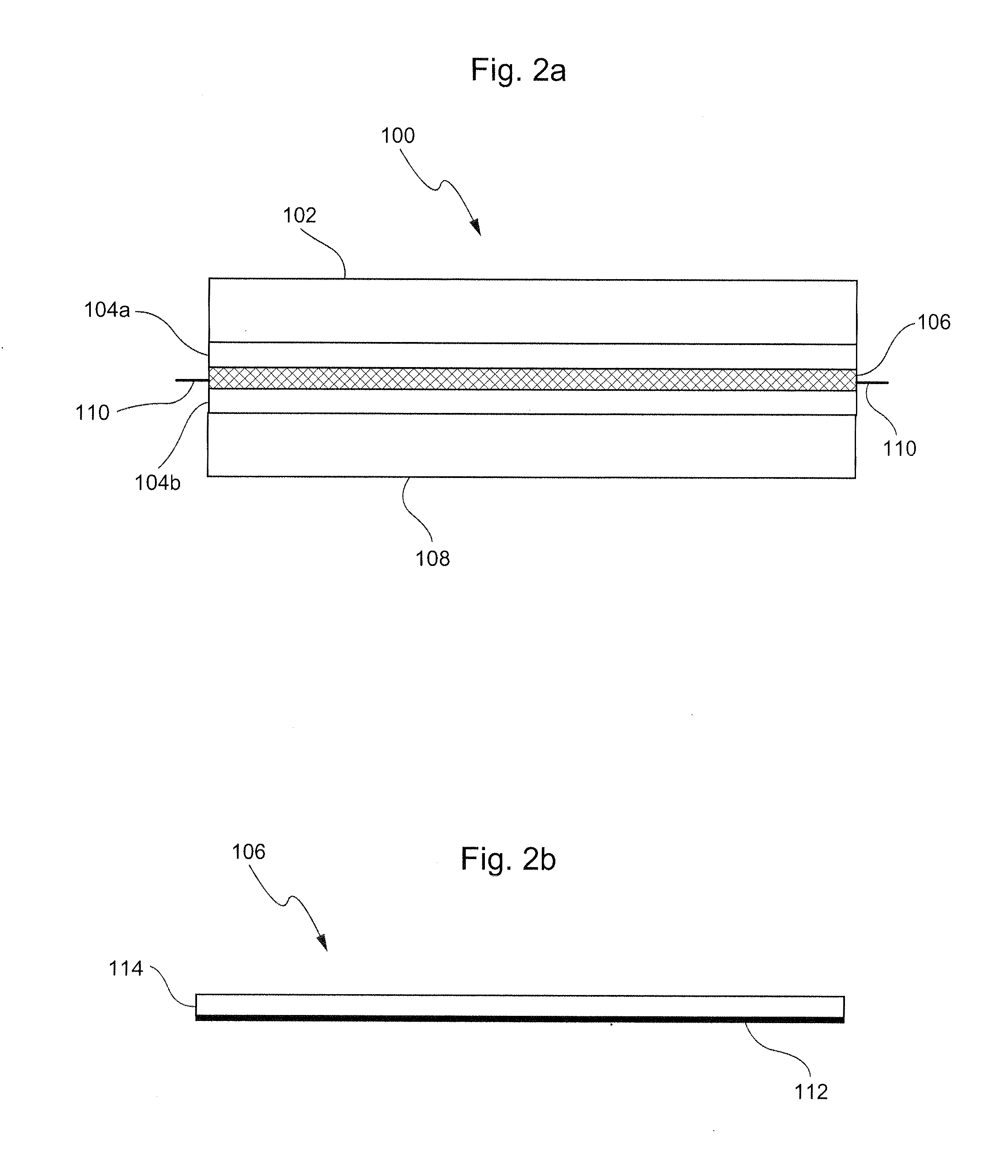
[0047]Certain example embodiments may relate to PV modules comprising two glass substrates, a PV layer disposed therebetween, and a bonding agent to bond the glass substrates and the PV layer together into one integrated PV module.

[0048]PV devices come in many forms. One area of PV devices is Thin Film Solar Cells (TFSC). Examples of TFSC devices include CIGS (Cu(In, Ga)(Se, S)2) and CIS (CuInSe2) solar cells.

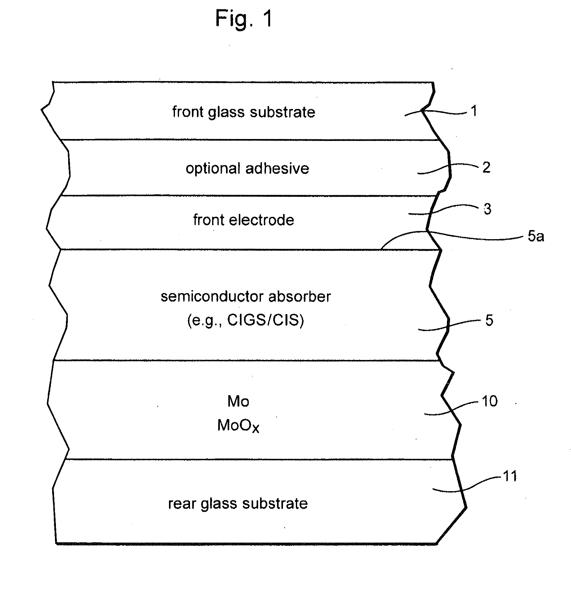
[0049]CIGS and CIS type photovoltaic devices may include, from the front or light incident side moving rearwardly, a front substrate of a material such as glass, a front electrode comprising a transparent conductive layer such as a TCO (transparent conductive oxide), a light absorption semiconductor film (e.g., CIGS and / or CIS film), a rear electrode, and a rear substrate of a material such as glass. Sometimes an adhesive is provided between the front substrate and the front electrode, and it is also possible for window layer(s) (e.g., of or including CdS, ZnO, or the like) to ...


PUM

PropertyMeasurementUnit
distanceaaaaaaaaaa
thicknessaaaaaaaaaa
thicknessaaaaaaaaaa

Abstract

Certain example embodiments relate to techniques for creating improved photovoltaic (PV) modules. In certain example embodiments and first and second glass substrate are provided. A PV array is provided between the first and second glass substrates. The first and second substrates are laminated together with the PV array between the glass substrates. In certain example embodiments the PV module is dimensioned to be similar to an existing roof system (e.g., a sunroof) in a vehicle. In certain example embodiments, holes are provided in a PV module sandwiched between two substrates, the holes being shaped and arranged within the PV module so as to allow light transmission into the vehicle at desired level while still being substantially filled by the laminate or adhesive material used to secure the PV module to the two surrounding substrates.

Description

[0001]This application is a continuation-in-part (CIP) of U.S. application Ser. No. 12 / 926,058 filed on Oct. 22, 2010, the entire contents of which are hereby incorporated by reference herein.FIELD OF THE INVENTION[0002]Certain example embodiments of this invention relate to improved photovoltaic (PV) modules for use in vehicle roofs, and / or methods of making the same. More particularly, certain example embodiments relate to PV modules for use on automotive, recreational, marine, and / or other vehicles, and / or methods of making the same. In certain example embodiments, holes are provided in a PV module sandwiched between two substrates, the holes being shaped and arranged within the PV module so as to allow light transmission into the vehicle at desired level while still being substantially filled by the laminate or adhesive material used to secure the PV module to the two surrounding substrates.BACKGROUND AND SUMMARY OF EXAMPLE EMBODIMENTS OF THE INVENTION[0003]Photovoltaic (PV) dev...

Claims


Application Information

Patent Timeline
Patent Type & Authority Applications(United States)
IPC IPC(8): H01L31/048H01L31/18
CPCC03B23/025H01L31/0488Y02E10/50Y02T10/88B32B17/10036Y10T156/1054B32B17/10761B32B17/10788B32B2457/12Y10T156/1067B32B17/10119Y02T10/90
Inventor BRECHT, GREGRUGGERO, II, VINCENT E.FREY, TIMOTHY J.VANDAL, ROBERT A.
Owner GUARDIAN GLASS LLC
Why Eureka
Try Eureka