Ladar sensor for landing, docking and approach

Active Publication Date: 2012-10-18
CONTINENTAL AUTONOMOUS MOBILITY US LLC
View PDF8 Cites 132 Cited by
  • Summary
  • Abstract
  • Description
  • Claims
  • Application Information

AI Technical Summary

Benefits of technology

[0005]The present invention comprises a flash ladar sensor with a number of innovations that produce an optimal performance in controlled approach, docking and landing applications. Additionally, the flash ladar sensor of the instant invention makes use of range gating techniques to penetrate through optical clutter such as aerosol clouds, blowing leaves, or sparse foliage. Range gating further enables underwater docking and bathometry. The result of these improvements is an improved range accuracy and better image quality of the flash ladar sensor for approach, landing, and docking in terrestrial, ocean surface, underwater and space environments.
[0006]The present invention is particularly relevant to the performance of both automatic and pilot-assisted landing, approach, and docking systems. Many attempts have been made to solve the problem of how to create the true 3-D imaging capability which would simultaneously enable all of the identified applications. The instant invention makes use of a number of new a

Problems solved by technology

However, this system is really a half duplex communication system or transponder, rather than a true r

Method used


Image

  • Ladar sensor for landing, docking and approach
  • Ladar sensor for landing, docking and approach
  • Ladar sensor for landing, docking and approach

Examples


Example

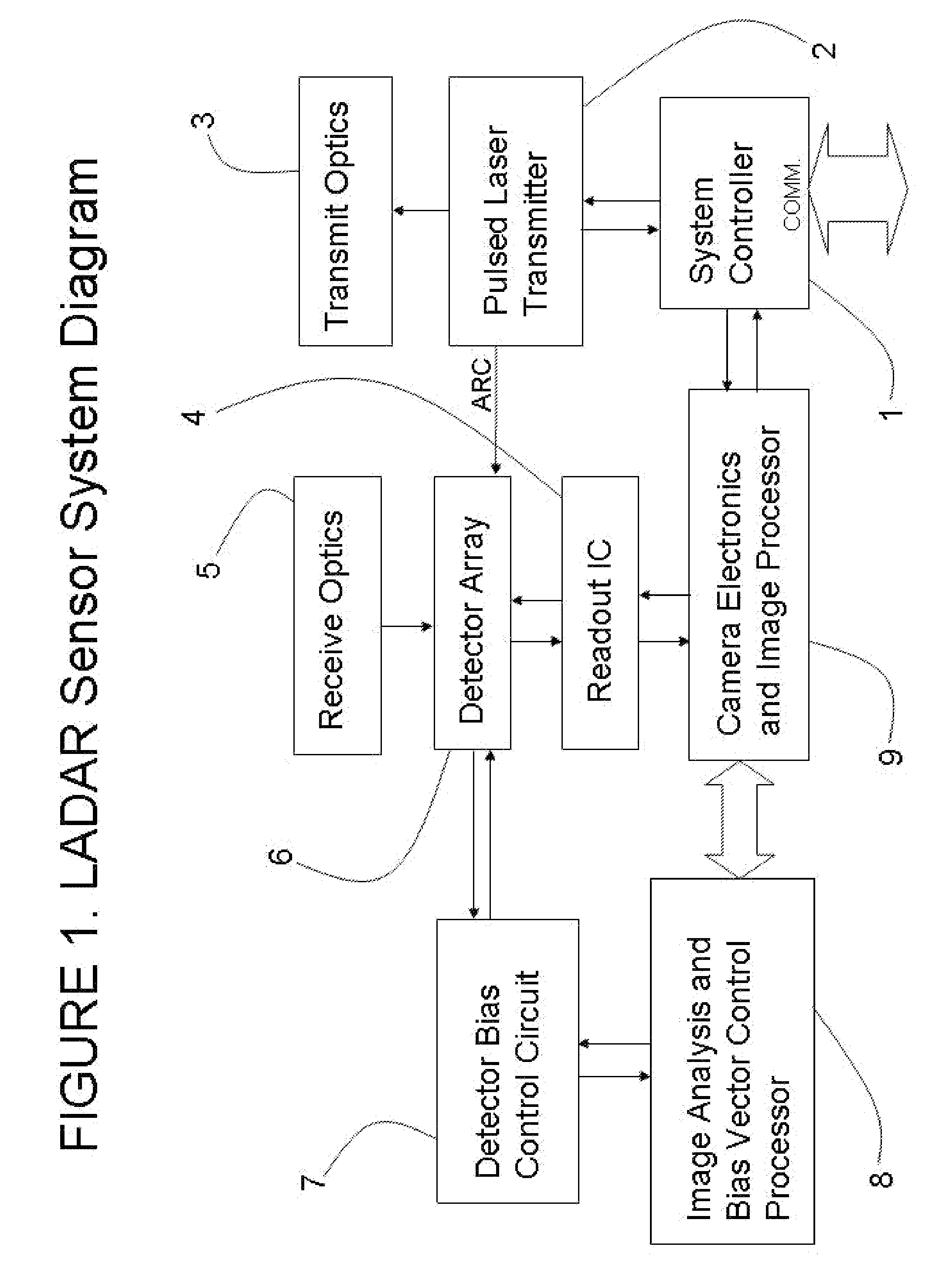
[0019]An embodiment of the present invention, the LADAR sensor for landing and approach is depicted in block diagram form in FIG.1. The system is designed to produce a series of 3-dimensional images using pulsed laser light, a pixelated imaging optical receiver responsive to light reflected from the scene in the field of view, and timing circuits associated with each pixel of the imaging optical receiver. The LADAR sensor for landing and approach is capable of producing range and intensity data for any object or scene within its field of view from a single pulse of pulsed laser transmitter 2, in conjunction with system controller 1, transmit optics 3, receiver optics 5, detector array 6, readout integrated circuit 4, camera electronics and image processor 9, image analysis and bias vector control processor 8, and detector bias control circuit 7. The abbreviated description “ladar sensor”, may be used as a shorthand reference to the “ladar sensor for landing and approach” of the inst...


PUM


Abstract

A system for landing or docking a mobile platform is enabled by a flash LADAR sensor having an adaptive controller with Automatic Gain Control (AGC). Range gating in the LADAR sensor penetrates through diffuse reflectors. The LADAR sensor adapted for landing/approach comprises a system controller, pulsed laser transmitter, transmit optics, receive optics, a focal plane array of detectors, a readout integrated circuit, camera support electronics and image processor, an image analysis and bias calculation processor, and a detector array bias control circuit. The system is capable of developing a complete 3-D scene from a single point of view.

Description

[0001]This application claims the priority date of U.S. Provisional Patent Application No. 61 / 475,955 filed Apr. 15, 2011.FIELD OF THE INVENTION[0002]The present invention relates to the field of remote sensing of objects and the application of lasers to the problems of 3-D imaging, remote object detection and definition, terrain mapping, bathometry, vehicle guidance, and collision / hazard avoidance.BACKGROUND OF THE INVENTION[0003]Many laser radar systems have been built which rely on the transmission of a high energy illuminating pulse. Most often these systems rely on solid state lasers operating in the near infrared with a lasing media of Neodymium-YAG or Erbium doped glass. Many of these systems utilize multiple pulses over a period of time to detect remote objects and improve range accuracy. These systems are often based on a single detector optical receiver. To develop a complete picture of a scene, the laser and optical receiver must be scanned over the field of view, resulti...

Claims


Application Information

Patent Timeline
IPC IPC(8): G06G7/70G01C3/08G01S7/4863G01S17/18G01S17/89
CPCG01S17/107G01S17/89G01S7/481G01S7/4868G01S17/88G01S7/4863G01S17/18B64G1/646B64D47/00B64D39/00
Inventor GILLILAND, PATRICKKOSELUK, BOBPENNIMAN, STEVESHORT, BRADSPAGNOLIA, JOESTETTNER, ROGER
Owner CONTINENTAL AUTONOMOUS MOBILITY US LLC
Why Eureka
Try Eureka