
Heat assisted narrow pole design with trailing shield

Active Publication Date: 2012-10-18
HEADWAY TECH INC
View PDF7 Cites 1 Cited by
  • Summary
  • Abstract
  • Description
  • Claims
  • Application Information

AI Technical Summary

Benefits of technology

[0023]It is a third object of the present invention to achieve the first two objects while providing a pole design that does not create significant adjacent track erasures (ATE).
[0026]The edge plasmon mode is excited in an overlap region between a conducting edge plasmon generator (EPG) and a waveguide (WG). The source of optical excitement can be a laser diode, also contained within the read / write head structure, or a laser source that is external to the read / write head structure, either of which directs its beam of optical radiation at the generator through a means of intermediate transfer such as an optical waveguide (WG). As a result of the WG, the light optical mode couples to a local plasmon mode of a propagating plasmon mode of a PG, whereby the optical energy is converted into plasmon energy. This plasmon energy is then transferred to the medium in the write-gap region of the pole tip, at which point the heating occurs at a very small spot size. When the heated spot on the medium is correctly aligned with the magnetic field produced by the narrow pole tip, TAMR is achieved.
[0028]The TAMR writer design of the invention is one in which the pole has a narrow shape that permits high areal densities to be achieved in present magnetic media by means of thermally assisted writing at moderately elevated temperatures. Specifically, this design is a heat assisted narrow magnetic pole with a trailing shield (and supplemental plasmon shield) in which the heating spot is delivered in the write gap by an edge plasmon generator (EPG). The EPG is formed as a conducting layer (a layer of electrically conductive material) contiguous with the magnetic core of the pole tip itself, so the thermal energy of the plasmon and the magnetic field of the tip can be closely aligned. The design of the head structure is uncomplicated and permits trailing edge recording with a trailing shield and high magnetic field gradient. Since the heating is below Tc, less laser power is required and better thermal stability of the head structure is obtained. With the localized heating in the write gap, the writer field and the gradient produced by the narrow pole are sufficient to switch the medium magnetization and write a good transition.

Problems solved by technology

This latter effect is the thermal instability of the extremely small regions on which information must be recorded, in order to achieve the required data densities.
Satisfying these requirements simultaneously may be a limiting factor in the further development of the present magnetic recording scheme used in state of the art hard-disk-drives (HDD).
If that is the case, further increases in recording area density may not be achievable within those schemes.
As it is still in the development stage, FePt magnetic recording medium suffers from many adverse properties, such as roughness, large grain size distribution, large variation in Tc (Curie temperature), large dHc / Hc and large switching field distributions.
These properties, when taken together, limit the linear density capability of the FePt medium compared to the state-of-the-art PMR medium that is granular CoCrPt based.
Thus, the head designs disclosed in the cited prior arts will find it difficult to achieve the desired high areal recording densities in conventional PMR media.

Method used


Image

  • Heat assisted narrow pole design with trailing shield
  • Heat assisted narrow pole design with trailing shield
  • Heat assisted narrow pole design with trailing shield

Examples


first embodiment

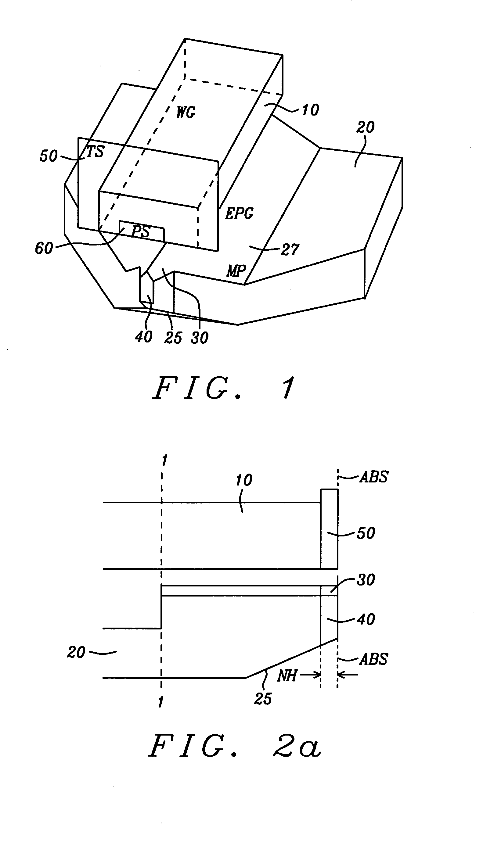
[0035]Referring to schematic FIG. 1, there is shown a 3-dimensional view of the heat-assisted magnetic write pole with a narrow pole tip design of the present invention. An optical waveguide, WG, (10) is positioned adjacent to (and separated from) the trailing edge side of the main pole (MP) (20). The shape of the MP (20) shows an upward sloped leading edge taper (25) and downward sloped side tapers (27). An edge plasmon generator (EPG) (30) is formed as a conducting layer conformally covering a substantial portion of the trailing edge of the MP, which can here be considered as extending over the side tapers (27). Note also that although the EPG has a thickness between approximately 5 nm and 80 nm, the thickness is not shown in this perspective drawing.

[0036]The region of coverage by the EPG, which includes coverage over the symmetric sides (27) of the MP and over the entire trailing edge surface of the narrow pole tip (40), overlaps with, but is separated from, a portion of the WG ...

second embodiment

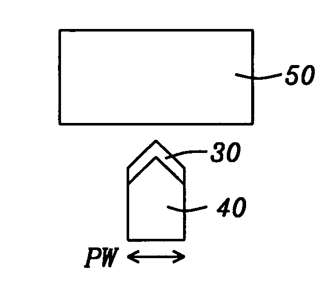
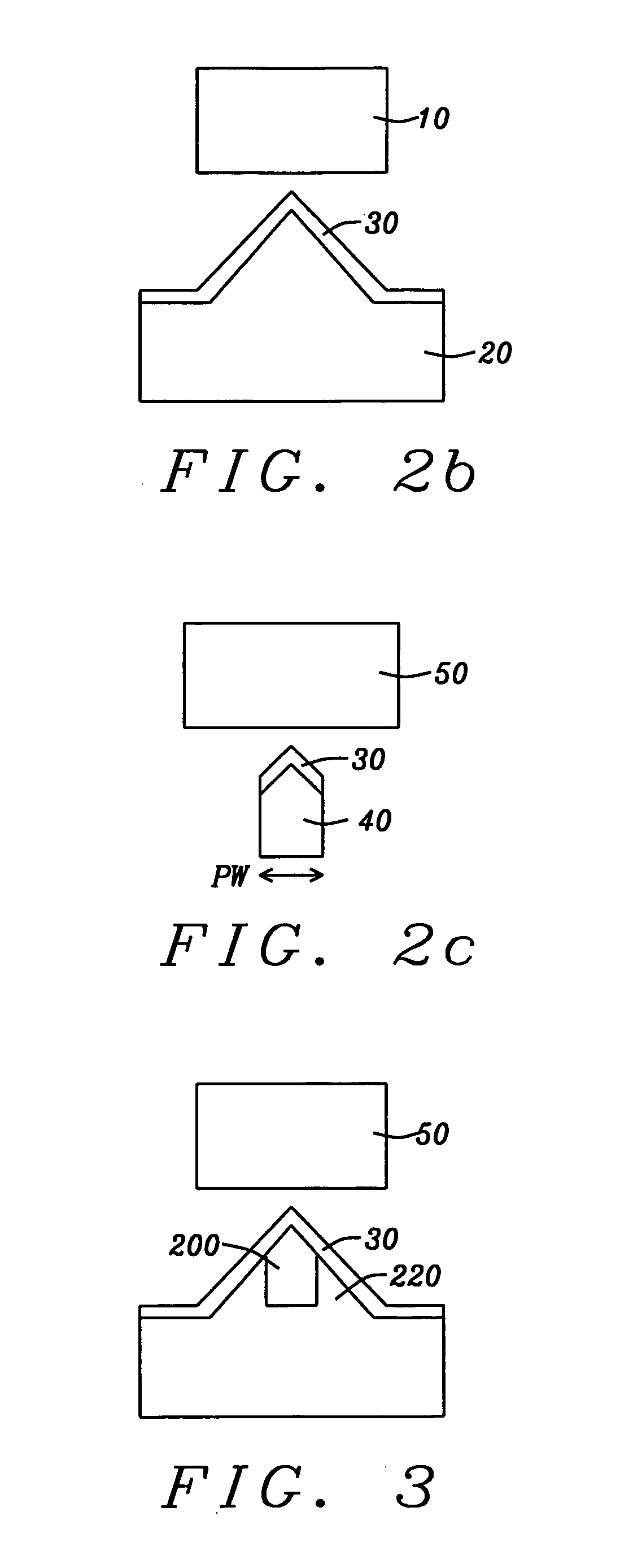
[0043]Referring to schematic FIG. 3, there is shown an alternative structure that forms a second embodiment of the invention. In this design, the magnetic pole is still tapered down to a narrow tip (200) of magnetic material at the ABS, but the EPG layer (30) retains the same cross-sectional dimension from the back end of the pole where it commences (i.e., as is shown in FIG. 2(b) for the first embodiment), to the ABS end (which is shown here in FIG. 3). The trailing shield (50) is shown above the pole tip. Maintaining the dimensions of the EPG layer is accomplished by filling the region around the etched pole tip with non-magnetic metals (220), such as Ta, Ti, Ru, Cr or any of their composites, to provide support for the EPG layer. It is to be noted that FIG. 3 is analogous to FIG. 2(c), in that it illustrates the ABS end of the pole in this second embodiment, just as FIG. 2(c) illustrates the ABS of the pole in the first embodiment. Superficially, FIG. 3 may look like FIG. 2(b), w...


PUM


Abstract

A TAMR (Thermal Assisted Magnetic Recording) writer has a narrow pole tip with a trailing edge magnetic shield. The narrow pole tipped write head uses the energy of laser generated edge plasmons, formed in a plasmon generating layer, to locally heat a PMR magnetic recording medium below its Curie temperature, Tc. When combined with the effects of the narrow tip, this local heating to a temperature below Tc is sufficient to create good transitions and narrow track widths in the magnetic medium. The write head is capable of writing effectively on state-of-the-art PMR recording media having Hk of 20 kOe or more.

Description

BACKGROUND OF THE INVENTION[0001]1. Field of the Invention[0002]This invention relates to the fabrication of magnetic read / write heads that employ TAMR (thermally assisted magnetic recording) to enable writing on magnetic media having high coercivity and high magnetic anisotropy. More particularly, it relates to the use of a narrow magnetic pole in conjunction with plasmon mode heating to obtain narrow track widths for recording at high densities.[0003]2. Description of the Related Art[0004]Magnetic recording at area data densities of between 1 and 10 Tera-bits per in2 involves the development of new magnetic recording media, new magnetic recording heads and, most importantly, a new magnetic recording scheme that can delay the onset of the so-called “superparamagnetic” effect. This latter effect is the thermal instability of the extremely small regions on which information must be recorded, in order to achieve the required data densities. A way of circumventing this thermal instabil...

Claims


Application Information

Patent Timeline
IPC IPC(8): G11B13/04G11B5/127G11B7/22B82Y10/00B82Y40/00
CPCB82Y10/00G11B5/3116G11B5/84G11B2005/0021G11B5/314
Inventor JIN, XUHUIZHOU, YUCHENTAKANO, KENICHISMYTH, JOE
Owner HEADWAY TECH INC
Learn More