Scatter correction methods

a scatter contamination and correction method technology, applied in image enhancement, image analysis, instruments, etc., can solve the problem of high frequency component of estimated error, and achieve the effect of reducing scatter contamination

Active Publication Date: 2012-10-18
GEORGIA TECH RES CORP
View PDF20 Cites 70 Cited by
  • Summary
  • Abstract
  • Description
  • Claims
  • Application Information

AI Technical Summary

Benefits of technology

[0005]The various embodiments of the present invention provide improved correction methods for reducing scatter contaminatio

Problems solved by technology

This high-frequency component of the estimated error can be error in spa

Method used


Image

  • Scatter correction methods
  • Scatter correction methods
  • Scatter correction methods

Examples


examples

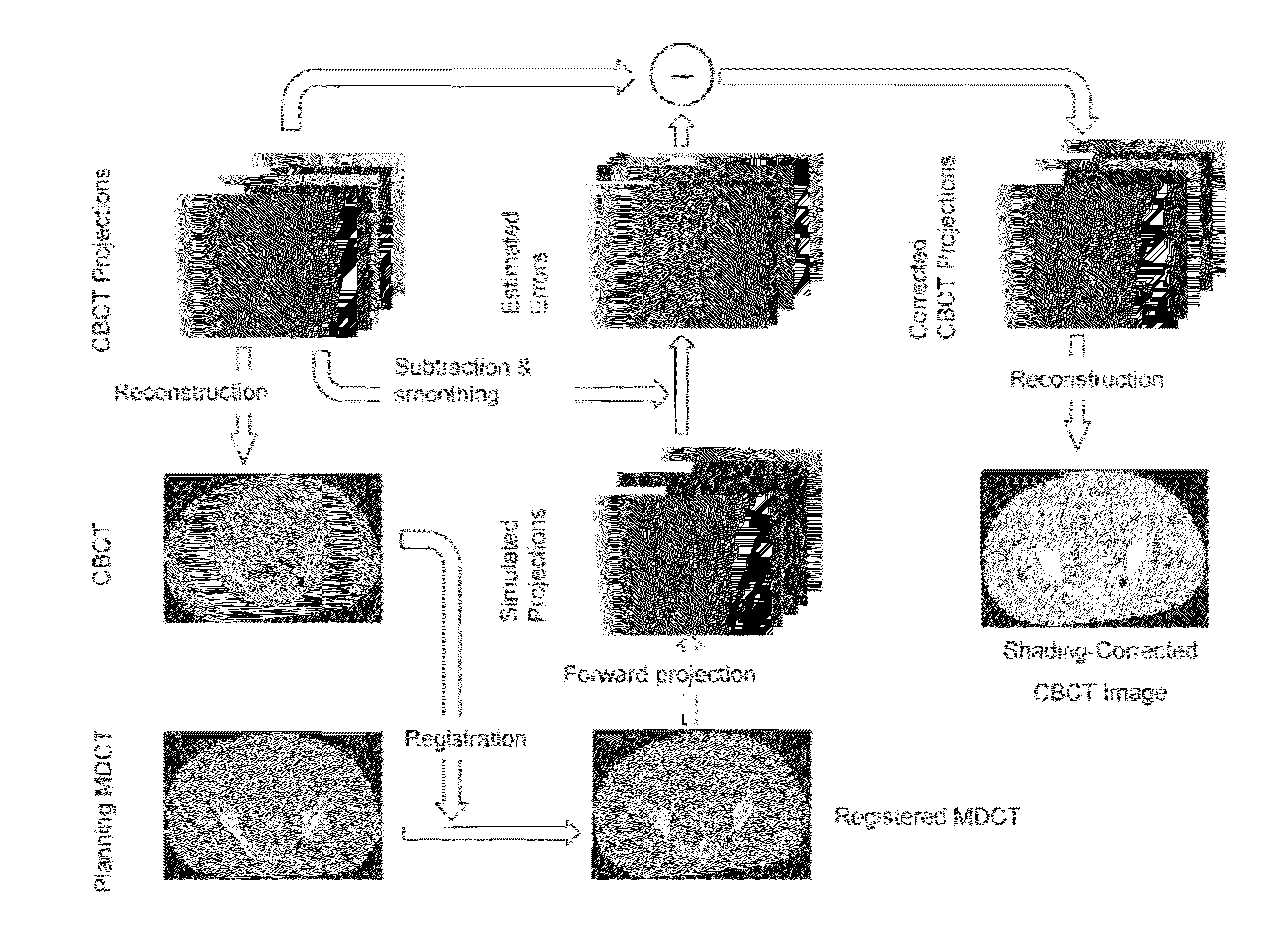
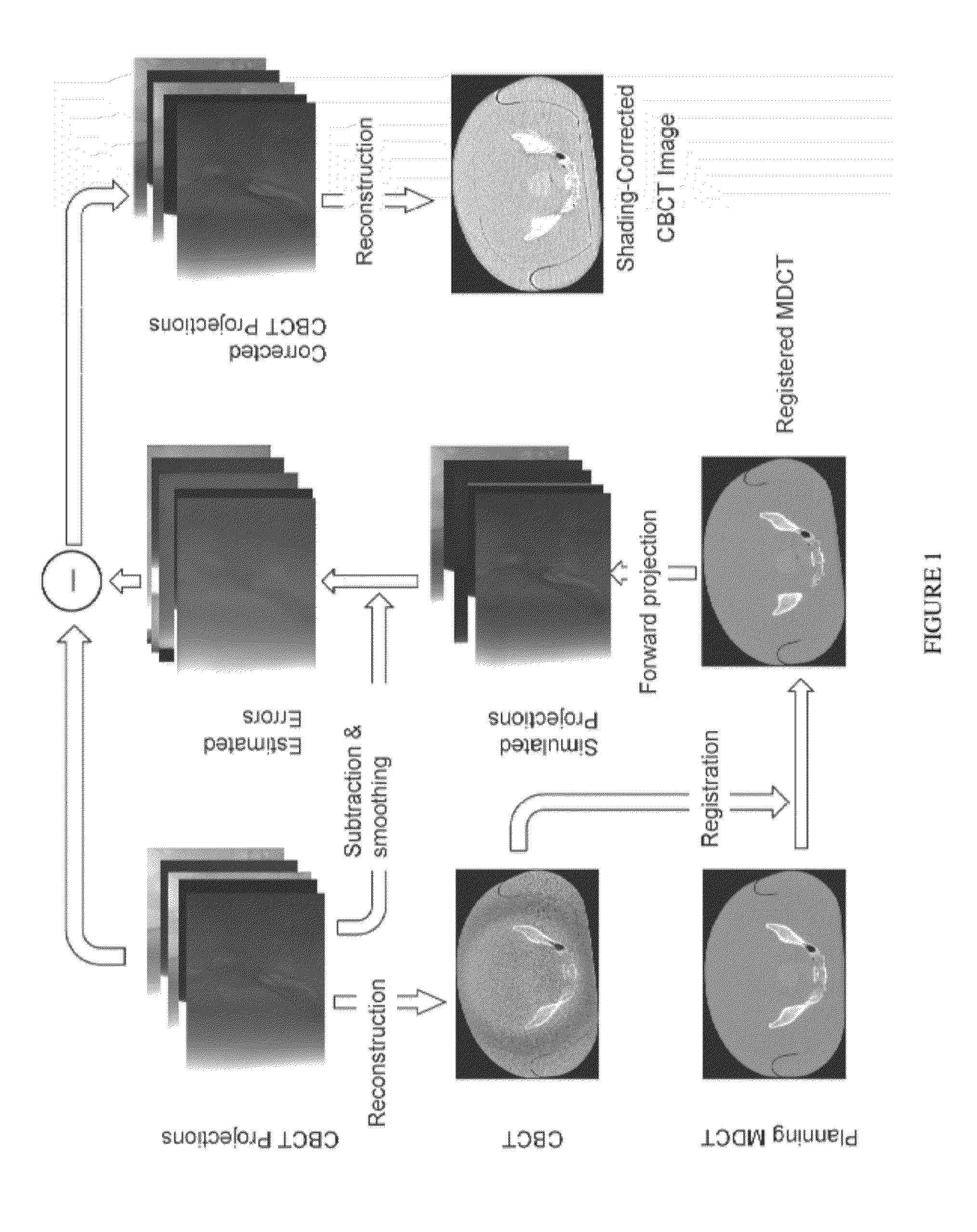
[0050]The method was evaluated using two phantom studies on CBCT tabletop systems. An evaluation phantom, Calphan©600, was used in the first study, and a detailed quantitative image analysis was carried out on the phantom inserts. The second study used an anthropomorphic pelvis phantom, for which shading correction was more challenging due to the high SPR and object heterogeneity.

[0051]For simplicity of description, the shading correction algorithm was derived assuming that scatter was the only source of errors in the projections while noting that other low-frequency errors from, for example, beam hardening effects and detector nonlinearities were also corrected.

[0052]The MDCT scanner was assumed a detector of 16 slices or less, with negligible scatter signals. With an anti-scatter collimator, the maximum SPR of MDCT was estimated to be on the order of ˜0.01. MDCT reconstruction algorithms can incorporate scatter, beam hardening and empirical uniformity corrections of their own to i...


PUM


Abstract

Described herein are improved methods for correcting cone beam computed tomography signals to reduce scatter contamination contained therein. Generally, the improved methods involve generating a plurality of two-dimensional projection images of a subject from a three-dimensional multi-detector computed tomography image of the subject. This is followed by subtracting the plurality of two-dimensional projection images from a plurality of two-dimensional cone beam projection images of the subject to produce a plurality of two-dimensional estimated error projections that comprise an estimated error in the plurality of two-dimensional cone beam projection images. The plurality of two-dimensional estimated error projection images are subtracted from the plurality of two-dimensional cone beam projection images to generate a plurality of two-dimensional corrected cone beam projection images. A three-dimensional corrected cone beam computed tomography image of the subject is then constructed from the plurality of two-dimensional corrected cone beam projection images.

Description

TECHNICAL FIELD[0001]The various embodiments of the present invention relate generally to methods for correcting X-ray imaging signals, including computed tomography (CT), and more particularly to methods for correcting such signals to reduce scatter contamination.BACKGROUND[0002]In image-guided radiation therapy (IGRT), on-board X-ray imaging has evolved from two to three dimensions, and cone-beam CT (CBCT) is being increasingly utilized to improve the therapy or treatment performance. CBCT imaging can be performed just before, during, or after treatment without moving the patient and is expected to yield more faithful and relevant patient images at treatment time compared to the planning multi-detector CT (MDCT) images taken before patients start their fractionated radiotherapy regimen. In current clinical practices, CBCT is used mainly to provide positioning information for treatment setup. In such cases, quantitative CBCT images with high CT number accuracies generally are not r...

Claims


Application Information

Patent Timeline
IPC IPC(8): G06K9/00
CPCG06T5/002G06T5/50G06T11/005G06T2207/20224G06T2207/10081
Inventor ZHU, LEINIU, TIANYE
Owner GEORGIA TECH RES CORP
Why Eureka
Try Eureka