
Methods and apparatus for the manipulation of particle suspensions and testing thereof

a particle suspension and particle technology, applied in the field of flow cytometry, ion channel electrophysiology, single cell electroporation, controlled shear force in vivo simulation cell culture, etc., can solve the problems of loss of subcellular information, significant slowing of technique, and inability to sort cells

Inactive Publication Date: 2012-10-18
FLUXION BIOSCI
View PDF5 Cites 26 Cited by
  • Summary
  • Abstract
  • Description
  • Claims
  • Application Information

AI Technical Summary

Benefits of technology

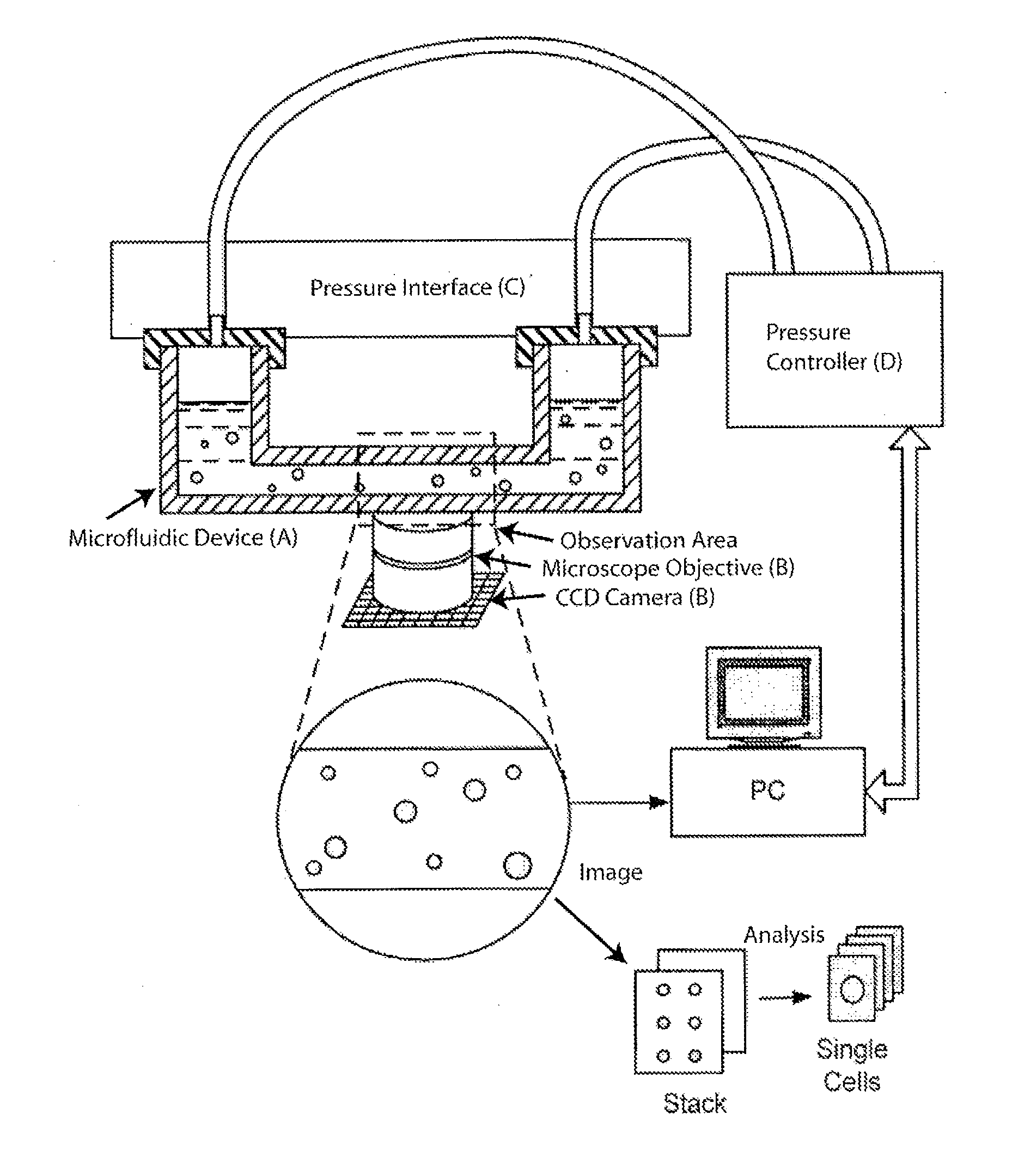
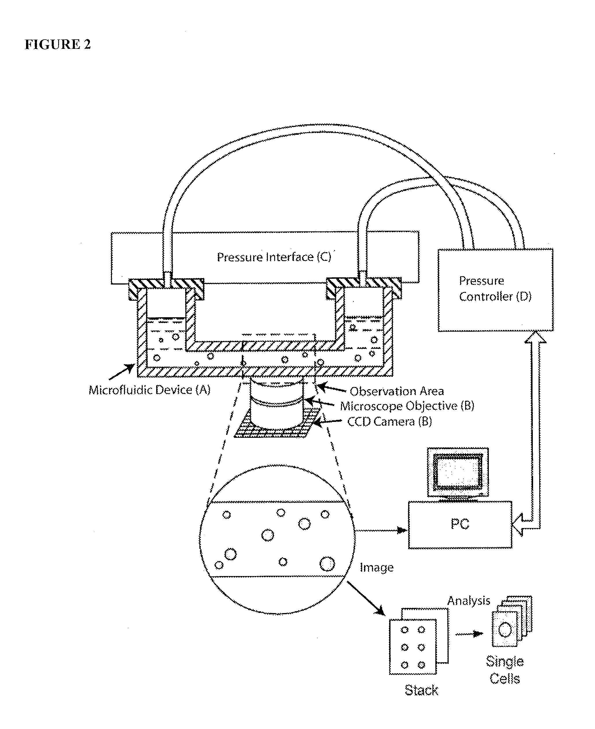
"The invention is a system for analyzing individual particles in suspension, which can be used to investigate dynamic processes at the cellular systems level and to engineer therapeutically useful cells for molecular medicine. The system includes a microfluidic device with individual addressability of particles, a plate with a multitude of reservoirs in fluid communication with the microfluidic device, and an interface detachably connectable to the microfluidic layer. The system can be used to analyze particles such as beads, cells, bacteria, vesicles, and embryos. The main technical effects of the invention include the ability to investigate particle behavior at a cellular level, the ability to engineer cells for therapeutic purposes, and the ability to perform particle imaging, counting, characterization, and classification."

Problems solved by technology

A key drawback of this technique is the loss of sub cellular information.
This technique is significantly slower as compared to flow cytometry, and requires automatic focus and due to movement of the substrate in the XY plane.
An additional drawback of this technique is the inability to sort cells.
The requirement of assembling in-flight images of single cells requires a great deal of custom technical development, which translates in a relatively high price for such devices (approx.
The problem with this approach is that the compounds are notoriously slow to diffuse through the membrane to reach this binding site (t>20 minutes).
Consequently, hERG measurements often fail due to the lack of long term stability for the high resistance seal between the glass pipette and the cell (seals often degrade in t<20 minutes).
Despite constant improvement of the traditional patch clamp technique, it remains laborious, requiring pipettes to be placed in the cell vicinity by a skillful operator using a micromanipulator under a microscope.
Consequently, the patch clamp technique has been difficult to use in drug development, where high-throughput automated measurements are required.
The most serious drawbacks of this approach its inability to work with mammalian cell lines as well as the complexity of the manipulation system, while savings in terms of reagent use are minimal.
Currently available automated electrophysiology devices are employed by large organizations at large capital expense (greater than $400,000 per instrument) as well as a large cost per data point (about $10 per cell trap).
They also retain important limitations in the area of optical observation and compound perfusion.
Before this can happen, however, significant challenges with respect to short interfering RNA (siRNA) delivery and targeting must be overcome.
Bulk electroporation requires very high voltages (kVolts) and has little control over the permeabilization of individual cells, resulting in suboptimal parameters.
Reversible electroporation, in which the pores can reseal, is therefore difficult [Chang, D. C.].
Currently single cell electroporation is performed using laborious manual setups.
Current practice suffers from limited throughput, cumbersome apparatus assembly, experiment failure (i.e. by bubble introduction), and a limited range of applicable shear forces.

Method used


Image

  • Methods and apparatus for the manipulation of particle suspensions and testing thereof
  • Methods and apparatus for the manipulation of particle suspensions and testing thereof
  • Methods and apparatus for the manipulation of particle suspensions and testing thereof

Examples


Embodiment Construction

[0150]The apparatus and methods described herein relate generally to the manipulation of particle suspensions (e.g., cell suspensions) and are useful for applications including but not limited to flow cytometry, ion-channel electrophysiology, single cell electroporation, controlled shear force in vivo-simulating cell culture and numerous related biotechnology approaches.

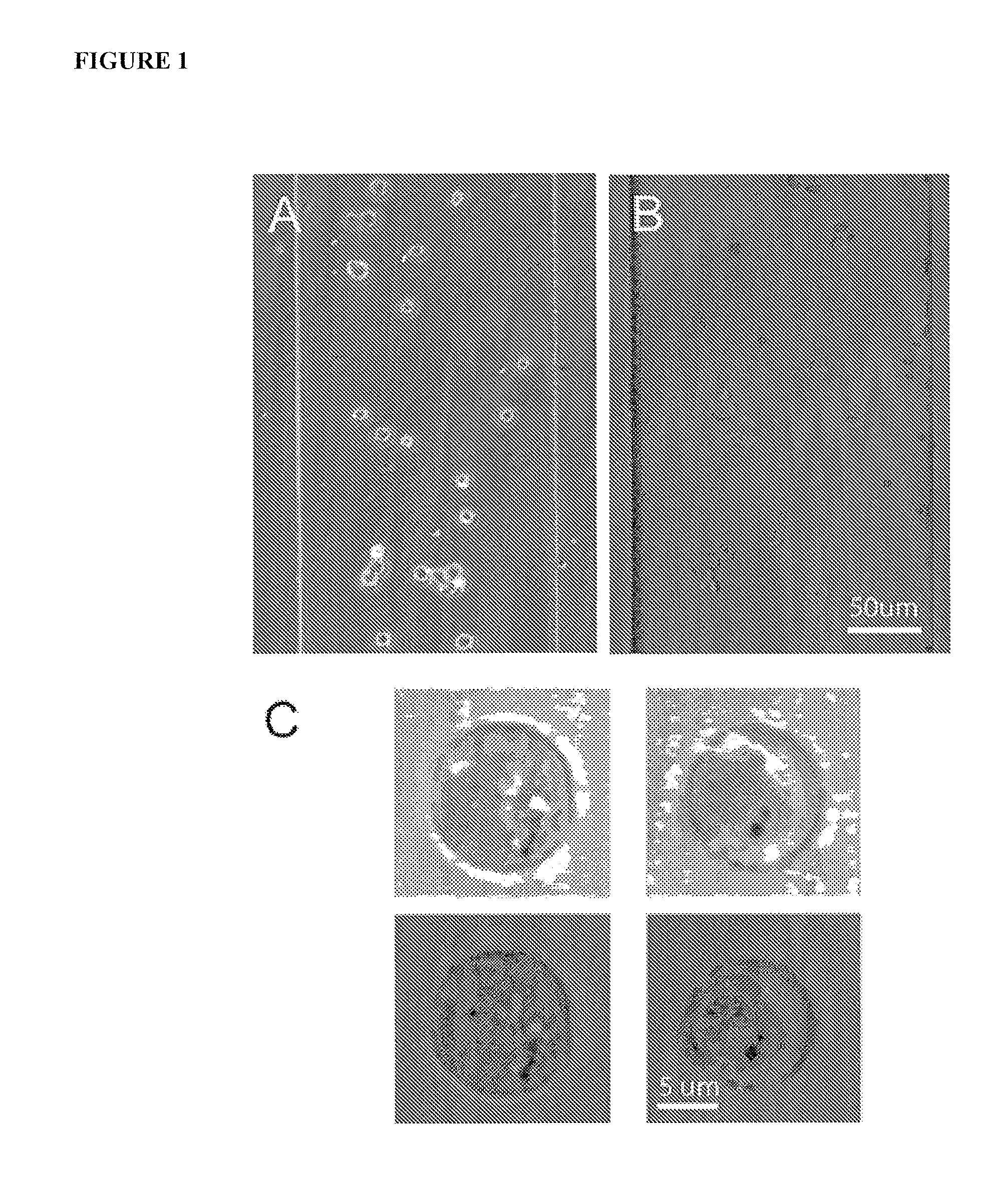
[0151]Recently introduced imaging flow cytometers aim to combine the speed and ease of use of flow cytometry with the high information content of Image Scanning Cytometry (Bonetta 2005). The instrument images cells as they flow by at high velocity in a single file. The requirement of assembling in-flight images of single cells requires a great deal of custom technical development, which translates in a relatively high price for such devices (approx. $300 k for Image Stream 100) and relegates their use to core labs and pharmaceutical companies.

[0152]Disclosed herein is an alternate technique that is based on accurate ...


PUM

PropertyMeasurementUnit
thicknessaaaaaaaaaa
depthaaaaaaaaaa
widthaaaaaaaaaa

Abstract

Apparatus and methods are provided for analysis of individual particles in a microfluidic device. The methods involve the immobilization of an array of particles in suspension and the application of experimental compounds. Such methods can also include electrophysiology studies including patch clamp recording, electroporation, or both in the same microfluidic device. The apparatus provided includes a microfluidic device coupled to a multi-well structure and an interface for controlling the flow of media within the microchannel device.

Description

CROSS-REFERENCE[0001]This application is a continuation of pending U.S. patent application Ser. No. 11 / 690,831, filed Mar. 25, 2007, which application claims the benefit of U.S. Provisional Application No. 60 / 744,034, filed Mar. 31, 2006, U.S. Provisional Application No. 60 / 868,864 filed Dec. 6, 2006, and U.S. Provisional Application No. 60 / 870,842 filed Dec. 19, 2006; these applications are incorporated herein by reference, in their entirety, for any purpose.STATEMENT AS TO FEDERALLY SPONSORED RESEARCH[0002]Funds used to support some of the studies disclosed herein were provided by grant number 1 R43 GM075509-01 awarded by the National Institutes of Health from the National Institute for General Medical Sciences. The Government may have certain rights in the invention.BACKGROUND OF THE INVENTION[0003]The fields of flow cytometry, ion-channel electrophysiology, single cell electroporation, controlled shear force in vivo-simulating cell culture and numerous related biotechnology appr...

Claims


Application Information

Patent Timeline
Patent Type & Authority Applications(United States)
IPC IPC(8): C12M1/42C12M1/34G01N27/26G01N21/00G01N21/64
CPCB01L3/5025C12M41/36B01L3/502738B01L3/502761B01L3/565B01L2200/027B01L2200/0647B01L2200/0668B01L2300/041B01L2300/046B01L2300/0627B01L2300/0645B01L2300/0654B01L2300/0829B01L2300/0861B01L2300/0864B01L2300/0867B01L2400/0487B01L2400/086G01N15/1459G01N15/1463G01N15/1484G01N2015/1075G01N2015/1495G01N2015/1497C12M21/06C12M23/16B01L3/502715C12M35/04G01N33/48728G01N2015/1027G01N15/1433G01N15/1409B01L3/50273B01L2200/025B01L2200/0689B01L2300/163G01N15/1404G01N2015/1006
Inventor IONESCU-ZANETTI, CRISTIANKHINE, MICHELLESCHWARTZ, MICHAEL
Owner FLUXION BIOSCI
Learn More