Systems for performing intralumenal reconstruction

a technology of intralumenal reconstruction and lumenectomy, which is applied in the field of intralumenal therapy for the treatment of vascular disease states, can solve the problems of long-term recanalization of aneurysms, hemorrhagic stroke, and symptomatic neurological deficits

Inactive Publication Date: 2012-10-18
EMPIRILON TECH
View PDF6 Cites 17 Cited by
  • Summary
  • Abstract
  • Description
  • Claims
  • Application Information

AI Technical Summary

Benefits of technology

[0016]In accordance with still another aspect of the present invention there is provided a method of reconstructing a body lumen having a defect using a stent device according to an embodiment of the present invention. The method comprises the steps of: positioning a stent device deployment system within a vessel adjacent a target site; applying fluid pressure to the interior lumen of the catheter; extending the balloon member from the catheter lumen longitudinally, thereby allowing a portion of the stent to be deployed adjacent the target site; retracting the catheter relative to the deployed portion of the stent; controlling the amount of overlap of the side extension members of the stent device during deployment of the stent adjacent the target site; releasing the stent device from the delivery catheter lumen; and releasing the stent from the balloon member.

Problems solved by technology

Under cerebral flow conditions the weakened vessel wall forms a bulge or aneurysm which can lead to symptomatic neurological deficits or ultimately a hemorrhagic stroke when ruptured.
One drawback associated with the use of bare embolization coils relates to the inability to adequately pack or fill the aneurysm due to the geometry of the coils which can lead to long term recanalization of the aneurysm with increased risk of rupture.
For instance, in the case of bioactive coils, the materials eliciting the biological healing response are somewhat difficult to integrate with the coil structure or have mechanical properties incompatible with those of the coil making the devices difficult to accurately position within the aneurysm.
This expansion may be immediate or time delayed but is generally, at some point, out of the control of the physician.
With a time delayed response the physician may find that coils which were initially placed accurately and detached become dislodged during the expansion process leading to subsequent complications.
For many aneurysms, such as wide necked or fusiform aneurysms the geometry is not suitable for coiling alone.
While these stent like devices have broadened the types of aneurysms amenable to embolization therapy, utilization of these devices in conjunction with embolization devices is technically more complex for the physician, may involve more risk to the patient and have a substantial cost increase for the healthcare system.
Stent devices of this nature while having the potential to reduce treatment costs have not been realized commercially due to the difficulty in manufacturing, reliability in delivering the devices to the treatment site and an inability to properly position the denser portion of the stent device accurately over the neck of the aneurysm.
While the aforementioned devices may have the ability to access the cerebrovasculature, they lack sufficient structural coverage of the lesion to achieve the desired patency of the vessel without the use of a balloon device.

Method used


Image

  • Systems for performing intralumenal reconstruction
  • Systems for performing intralumenal reconstruction
  • Systems for performing intralumenal reconstruction

Examples


Embodiment Construction

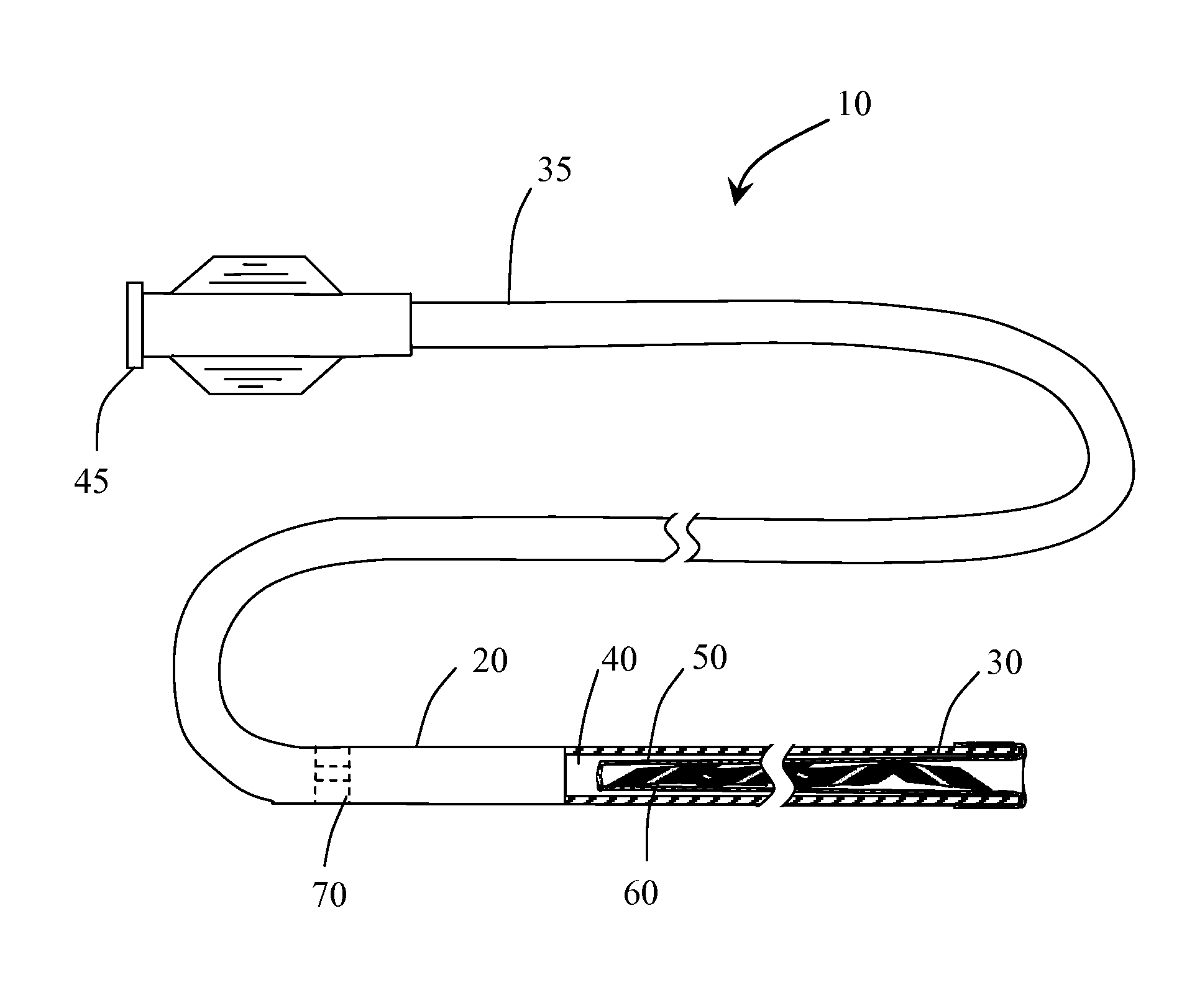
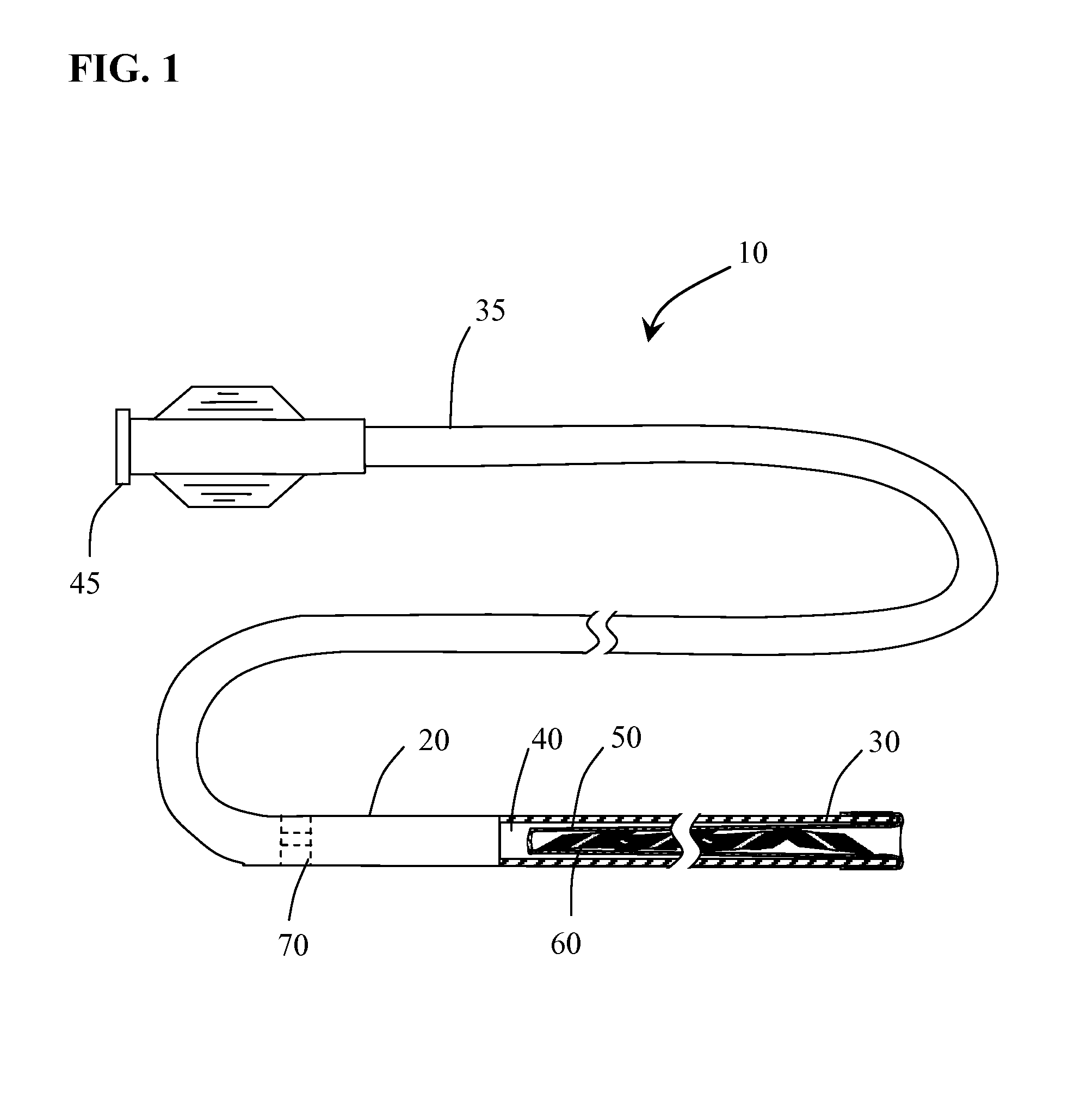
[0028]Methods and systems for performing vascular reconstruction and revascularization in a desired area of the body are herein described. FIG. 1 illustrates a medical device deployment system 10 suitable for use with embodiments of the present invention. Deployment system 10 includes an elongate tubular catheter 20 having distal and proximal ends 30 and 35 respectively and a through lumen 40 providing fluid communication between the catheter proximal hub 45 and balloon 50 which is everted and positioned within lumen 40 at distal end 30. While catheter 20 is shown having a single lumen 40 it should be understood that catheter 20 may incorporate additional lumens as needed. For instance catheter 20 may be formed from a dual lumen extrusion in which one lumen is used for coupling to balloon 50 and the second lumen to facilitate use of a guidewire for navigating the catheter to a target site. Alternatively, the second lumen may not extend the full length of the catheter and may only be...


PUM


Abstract

Devices, systems and methods are provided for performing intra-lumenal medical procedures in a desired area of the body. Stents, stent delivery devices and methods of performing medical procedures to redirect and or re-establish the intravascular flow of blood are provided for the treatment of hemorrhagic and ischemic disease states.

Description

CROSS-REFERENCE TO RELATED APPLICATIONS[0001]This application claims the benefit of U.S. Provisional Application No. 61 / 501,732 filed Jun. 27, 2011, U.S. Provisional Application No. 61 / 501,736 filed Jun. 27, 2011 and U.S. Provisional Application No. 61 / 501,738 filed Jun. 27, 2011 all of which are hereby incorporated by reference herein in their entireties.[0002]This application is a continuation in part of International Application No. PCT / US2011 / 022255 filed Jan. 24, 2011, which claims the benefit of U.S. Provisional Application No. 61 / 298,046 filed Jan. 25, 2010 and U.S. Provisional Application No. 61 / 298,060 filed Jan. 25, 2010 all of which are hereby incorporated by reference herein in their entireties.BACKGROUND OF THE INVENTION[0003]The field of intralumenal therapy for the treatment of vascular disease states has for many years focused on the use of many different types of therapeutic devices. While it is currently unforeseeable that one particular device will be suitable to ...

Claims


Application Information

Patent Timeline
Patent Type & Authority Applications(United States)
IPC IPC(8): A61F2/84
CPCA61F2220/005A61F2220/0058A61F2/88A61F2/958A61F2/966A61F2002/823A61F2/91
Inventor JONES, DONALD K.MITELBERG, VLADIMIR
Owner EMPIRILON TECH
Why Eureka
Try Eureka