Method and apparatus for preventing scale deposits and removing contaminants from fluid columns

a technology of fluid column and scale, applied in the direction of quarries, separation processes, treatment water, etc., can solve the problems of affecting the operation of equipment, affecting the efficiency and labor of fouled systems, and affecting the efficiency of fluid treatment, so as to improve the efficiency of apparatus, improve the effect of fluid treatment, and reduce the effect of contaminant concentration

Inactive Publication Date: 2012-10-25
WILSA HLDG
View PDF5 Cites 3 Cited by
  • Summary
  • Abstract
  • Description
  • Claims
  • Application Information

AI Technical Summary

Benefits of technology

[0009]U.S. Pat. Nos. 6,706,196, 6,730,205, 6,852,235 and 7,407,589 and U.S. Patent Application No. 20080264869 disclose fluid treatment methods and apparatus utilizing magnetic energy concentrated in a plurality of distinct areas along a fluid flow path. The synergy of concentrated magnetic energy in concert with methods and apparatus of pulsed fluid treatment providing at least one region of pulsed fluid treatment within a fluid treatment chamber has been discovered to improve a wide variety of fluid treatment applications.
[0013]The instant method of pulsed fluid treatment comprises providing a fluid treatment vessel defining a fluid impervious boundary wall with an inner surface and having a fluid input port and a fluid output port, the inner surface of said fluid impervious boundary wall establishing a fluid treatment chamber; providing at least one transducer to direct pulsed fluid treatment proximate at least one distinct region within the fluid treatment chamber, said at least one transducer having a first conductor lead and a second conductor lead; providing at least one electrical energizing unit having a capacity to produce at least one distinct programmable output of electrical energy continuously switched on and off at a pulsed repetition rate to establish at least one pulsed electrical signal; providing at least one shielding material member, at least one shielding material member each having a capacity to restrict radiation of the at least one pulsed electrical signal, said at least one shielding material member further reducing external interference with said at least one pulsed electrical signal; providing means for deploying the at least one transducer within the fluid treatment chamber; providing means for deploying the at least one shielding material member to restrict propagation of the at least one pulsed electrical signal.
[0016]The means of energizing the coiled electrical conductor, along with the repetition rate, wavelength, amplitude and direction of the at least one pulsed electrical signal, may be adjusted to treat a variety of fluids. The instant invention may be utilized to improve the efficiency of apparatus utilized in solid / liquid phase separation or liquid / liquid separation, such as oil / water separation, and may also be effective in controlling and eliminating many biological contaminants. The instant invention typically will not over treat or under treat a feedstock, requires little monitoring or adjustment for effective fluid treatment and may be utilized in either single pass or and closed-loop fluid transmission systems.

Problems solved by technology

Suspended and dissolved minerals precipitate out of the water and accumulate as deposits of scale on the surfaces of thermal exchange system components and restrict the flow of water, act as insulation that inhibits heat transfer from one surface to another, impede the operation of equipment and increase energy consumption as the fouled systems lose efficiency and labor to meet operational parameters.
Fouled heat exchange systems must undergo descaling processes to recover lost productivity and reduce energy consumption at a significant expense, not only for the cost of cleaning system components but also for lost productivity while a facility is out of service as the fouled thermal exchange system is descaled.
Utilization of chemicals is costly, requires the storage, handling and dispensing of dangerous substances and poses increasing environmental concerns.
As chemicals, minerals and other contaminants accumulate in thermal exchange systems, the water becomes unsuitable for continued use and a fresh supply of water is required for the ongoing operation of such systems.
Contaminant laden water from such systems typically incurs large surcharges for wastewater disposal due to the treatment needed to render the water suitable for discharge into the environment.
Over time, deposits of scale and other contaminants form within the separation equipment used to remove water from oil, conduits utilized to return water to the formation and pipelines used to transport crude oil to a refinery; resulting in restricted fluid flow, limited capacity of fluid transmission systems and the deterioration of pumps, valves, meters and other equipment.
Productivity is lost when costly physical cleaning and chemical remediation are required to restore full flow to petroleum production and transmission systems.
Refineries, as well as other industrial complexes, are constantly challenged with remediation of hydrocarbon contaminants that migrate into storm water and wastewater systems.
However, prior art magnetic field generators are challenged by a number of deficiencies.
If the velocity of the fluid fails to match the configuration of the permanent magnets, such prior art devices typically fail to provide effective fluid treatment.
However, electrically energized coils generate heat, and the generation and retention of heat produced by the energized coil of an electromagnet has been a major limitation in the development of prior art devices attempting to generate high gauss for fluid treatment.
Heat retention commonly leads to the failure of prior art electromagnet devices when an overheated coil melts and creates a short circuit generating little magnetic energy, or separates and creates an open circuit generating no magnetic energy.
However, reducing the voltage and the associated flow of current through a coil results in fewer amp-turns of a prior art device, resulting in substantially lower gauss generation.
The low strength of the magnetic energy provided by such devices typically results in ineffective fluid treatment.
Another prior art method and apparatus use a length of wire coiled around the outer surface of a pipe to form an antenna that is then energized with electrical energy switched on and off at a frequency of 2 kHz-20 kHz in an effort to replace chemical treatment, but are challenged by a number of deficiencies.
Amplification merely results in the signal radiating farther from the coiled wire and typically fails to treat a broader cross section within a large diameter conduit.
Further, such prior art devices fail to shield the signals they generate and are susceptible to interference from stronger signals of other devices that can limit the efficiency of the fluid treatment they provide.
The unshielded signals of prior art devices also radiate from the coil and may interfere with radio controlled devices, such as apparatus utilized in telemetering data and equipment.

Method used


Image

  • Method and apparatus for preventing scale deposits and removing contaminants from fluid columns
  • Method and apparatus for preventing scale deposits and removing contaminants from fluid columns
  • Method and apparatus for preventing scale deposits and removing contaminants from fluid columns

Examples


first embodiment

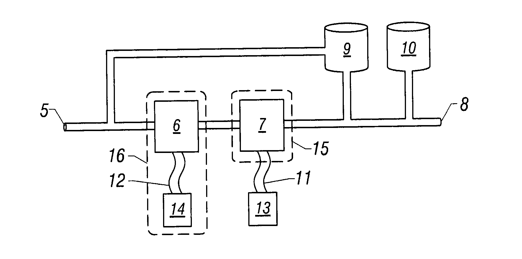
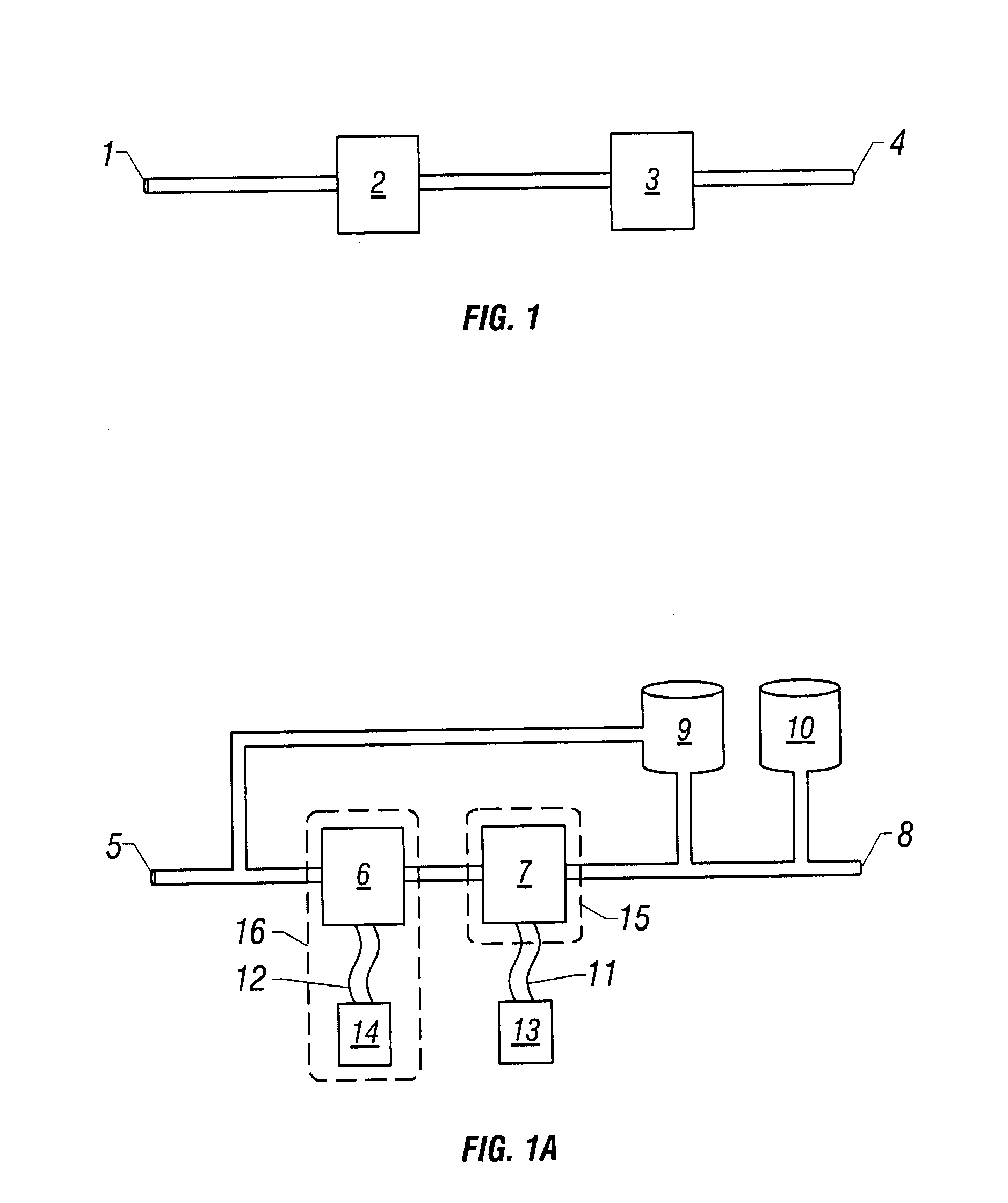
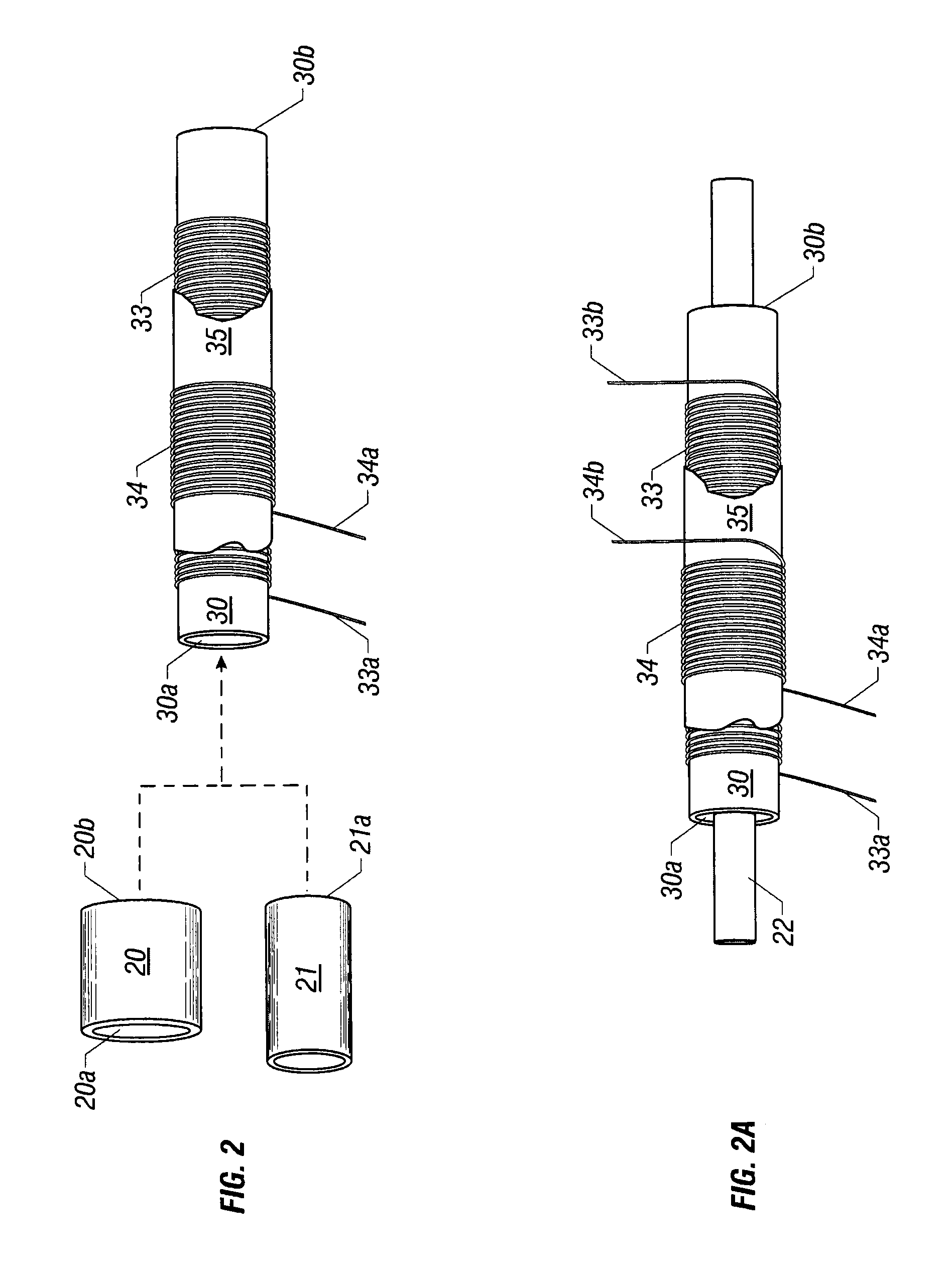
[0042]FIG. 2 shows the magnetically conductive conduit 10 comprising a length of magnetically conductive material defining a fluid impervious boundary wall with an inner surface and an outer surface and having port 10a at the proximal end of the conduit and port 10b at the distal end of the conduit. A single length of electrical conducting material is shown forming first coil layer 33 and second layer 34 encircling the outer surface of the magnetically conductive conduit with non-magnetic stabilizer 35 shown disposed between the coil layers. Conductor leads 33a and 34a may be connected to at least one supply of electrical power to energize the coiled electrical conductor and establish a magnetic field having lines of flux directed along the flow path of the fluid and concentrated in a plurality of distinct areas along the longitudinal axis of the magnetically energized conduit.

[0043]Introducing a feed stream to port 30a directs fluid to pass through a first area of magnetic treatmen...

second embodiment

[0045]Non-magnetically conductive conduit 21 is a non-magnetically conductive fluid flow conduit to promote a flow of fluid through the magnetically energized conduit, said fluid flow conduit comprising a non-magnetically conductive material defining a fluid impervious boundary wall with an inner surface and an outer surface and having port 21a adapted to provide for the fluid impervious connection of said fluid flow conduit with port 30a of magnetically energized conduit 30, whereby said connection establishes a non-magnetically conductive region providing for a concentration of magnetic energy at port 30a of the magnetically energized conduit. An additional segment of non-magnetically conductive fluid flow conduit may similarly be adapted to provide a fluid impervious connection with port 30b of the magnetically energized conduit.

[0046]FIG. 2A shows a first length of electrical conducting material forming coil layer 33 and a second length of electrical conducting material forming ...

third embodiment

[0048]Fluid flow conduit 22 is a non-magnetically conductive fluid flow conduit to promote a flow of fluid through the magnetically conductive conduit, said fluid flow conduit defining a section of conduit within a piping system comprising a non-magnetically conductive material sleeved within port 30a at the proximal end of the magnetically energized conduit, the boundary wall of magnetically conductive conduit 30 and port 30b at the distal end of the magnetically energized conduit, said fluid flow conduit comprising a length of non-magnetically conductive material defining a fluid impervious boundary wall with an inner surface and an outer surface and having inlet and outlet ports.

[0049]Introducing a feed stream to the inlet port of fluid flow conduit 22 directs fluid to pass through a first area of magnetic treatment concentrated at port 30a at the proximal end of magnetically energized conduit 30, through a second area of magnetic treatment concentrated along a path extending thr...


PUM


Abstract

A method and apparatus provide fluid treatment at a plurality of distinct points utilizing magnetic energy concentrated in a plurality of distinct areas along a fluid flow path and at least one region of pulsed fluid treatment within a fluid treatment chamber. The instant invention prevents the formation and accumulation of contaminants within conduits and on equipment utilized in the transportation, delivery and processing of fluid columns. It may also be utilized to accelerate the separation of oil and water and increase the efficiency of oil / water separation equipment.

Description

BACKGROUND OF THE INVENTION[0001]The instant invention relates to a method and apparatus for treating fluid columns to prevent the formation of scale and other flow restricting deposits within conduits utilized in the transmission of fluids. The instant method and apparatus may also be utilized to extract deposits from the surfaces of conduits and other components of fluid transmission systems, accelerate the separation of contaminants from a fluid and reduce the amount of chemicals required for the maintenance, treatment and processing of many fluids.[0002]Thermal exchange systems comprising components such as boilers, heat exchangers and cooling towers utilize water as a heat transfer medium. Suspended and dissolved minerals precipitate out of the water and accumulate as deposits of scale on the surfaces of thermal exchange system components and restrict the flow of water, act as insulation that inhibits heat transfer from one surface to another, impede the operation of equipment ...

Claims


Application Information

Patent Timeline
Patent Type & Authority Applications(United States)
IPC IPC(8): B03C1/02C02F1/48
CPCC02F2201/483C02F2103/10C02F1/48C02F1/484B03C1/0335C02F2103/023C02F1/487B03C2201/18C02F1/485C02F5/00C02F2103/02C02F2101/32C02F2303/22B03C1/02B01D35/06B03C1/288C02F2103/16
Inventor HOLLAND, HERBERT WILLIAM
Owner WILSA HLDG
Why Eureka
Try Eureka