Electric power steering apparatus

a technology of electric power steering and electric motor, which is applied in the direction of steering initiation, instruments, vessel construction, etc., can solve the problems of low performance of the disclosed second motor drive means, and increasing the space required for installation of redundant electric power steering mechanisms. , to achieve the effect of improving driving feeling, easy generation, and smooth operation

Inactive Publication Date: 2012-10-25
HONDA MOTOR CO LTD
View PDF6 Cites 52 Cited by
  • Summary
  • Abstract
  • Description
  • Claims
  • Application Information

AI Technical Summary

Benefits of technology

[0034]The second electric motor drive signal generator is capable of operating prior to the first electric motor drive signal generator suffering a failure. When the first electric motor drive signal generator suffers a failure, the first electric motor drive signal may instantaneously switch to the second electric motor drive signal, which is generated by the second electric motor drive signal generator. Accordingly, no delay occurs when the first electric motor drive signal switches to the second electric motor drive signal, thereby allowing the electric power steering apparatus to operate smoothly and continuously upon switching from the first electric motor drive signal to the second electric motor drive signal.
[0035]Each of the first electric motor drive signal and the second electric motor drive signal preferably comprises a PWM signal. Such a PWM signal may easily be generated by a microcomputer or a circuit made up of discrete components.
[0036]The steering torque sensor may comprise a magnetostrictive torque sensor for detecting the steering torque of the steering system based on a change in the magnetic permeability thereof. In such a case, the steering torque sensor is constructed of a small number of parts having a small-scale structure. Even if a microcomputer-based control process performed by the electric power steering apparatus is stopped, thereby disabling a control process such as an inertia correction control process, which improves feeling during driving, the torsional rigidity between the steering wheel of the steering system and the electric motor, which has a large moment of inertia, is increased, a delay in steering action is reduced, and a favorable steering sensation is maintained.
[0037]According to the present invention, in the event of a failure of the first electric motor drive signal generator, which belongs to the main system, the electric motor driver continues to drive the electric motor based on the second electric motor drive signal, which is generated by the second electric motor drive signal generator belonging to the redundant system, and which directly converts the steering torque signal generated by the torque sensor circuit into the second electric motor drive signal that changes depending on the magnitude of the steering torque signal. Therefore, even in the event of a failure of the first electric motor drive signal generator belonging to the main system, it is possible to apply an assistive steering force depending on the steering torque to the steering system with a simple, small, and highly reliable arrangement, i.e., a less failure-prone arrangement, using the second electric motor drive signal generator belonging to the simpler redundant system.

Problems solved by technology

Therefore, the disclosed second motor drive means is low in performance and has much to be improved.
In addition, changing the polarity of the DC voltage requires a large-capacity power relay for switching between large electric currents each time that the steering wheel is turned.
Such a large-capacity power relay results in an increased space required for installation of the redundant electric power steering mechanism.

Method used


Image

  • Electric power steering apparatus
  • Electric power steering apparatus
  • Electric power steering apparatus

Examples


1st embodiment

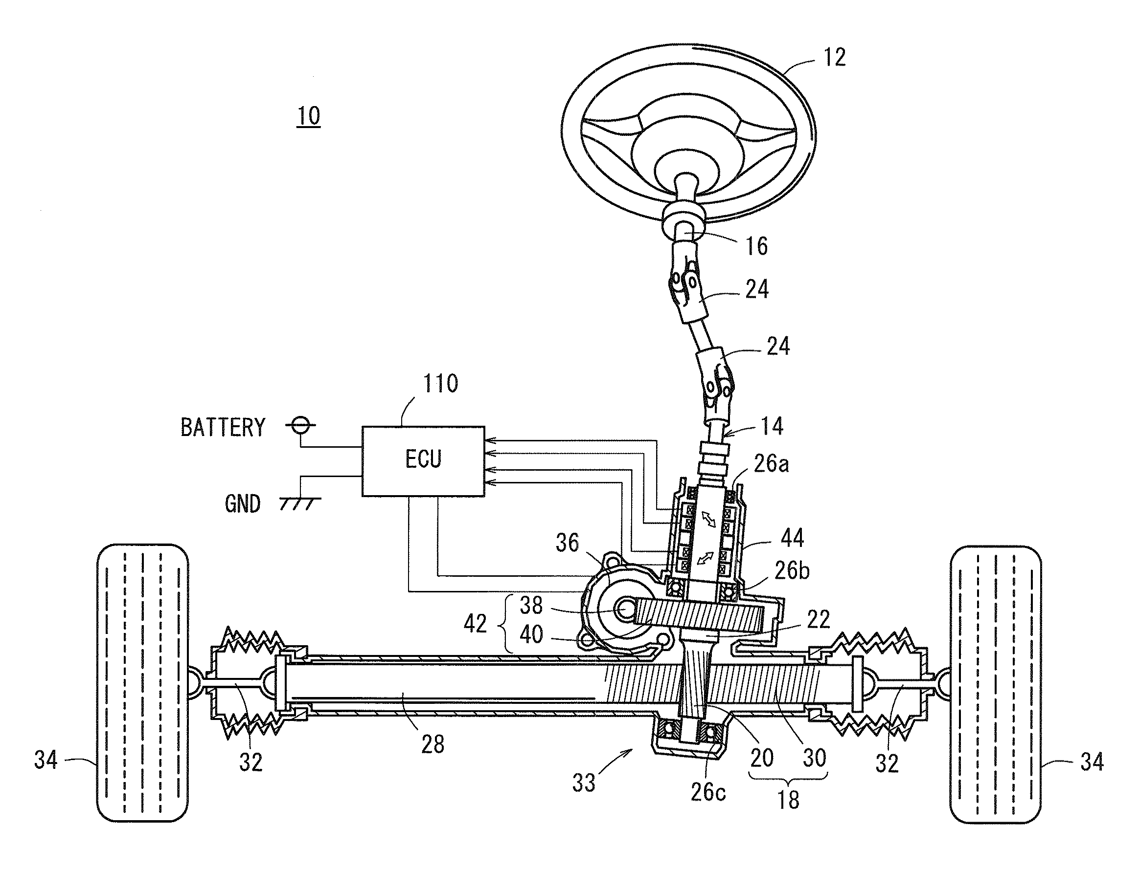
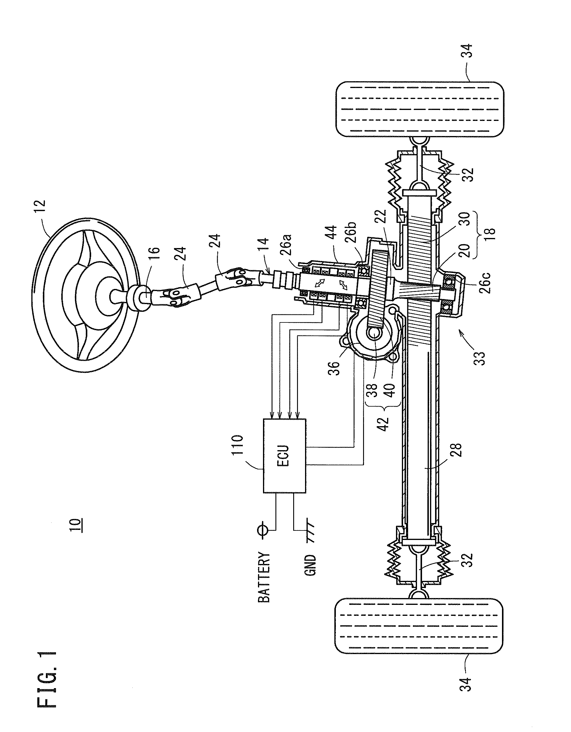
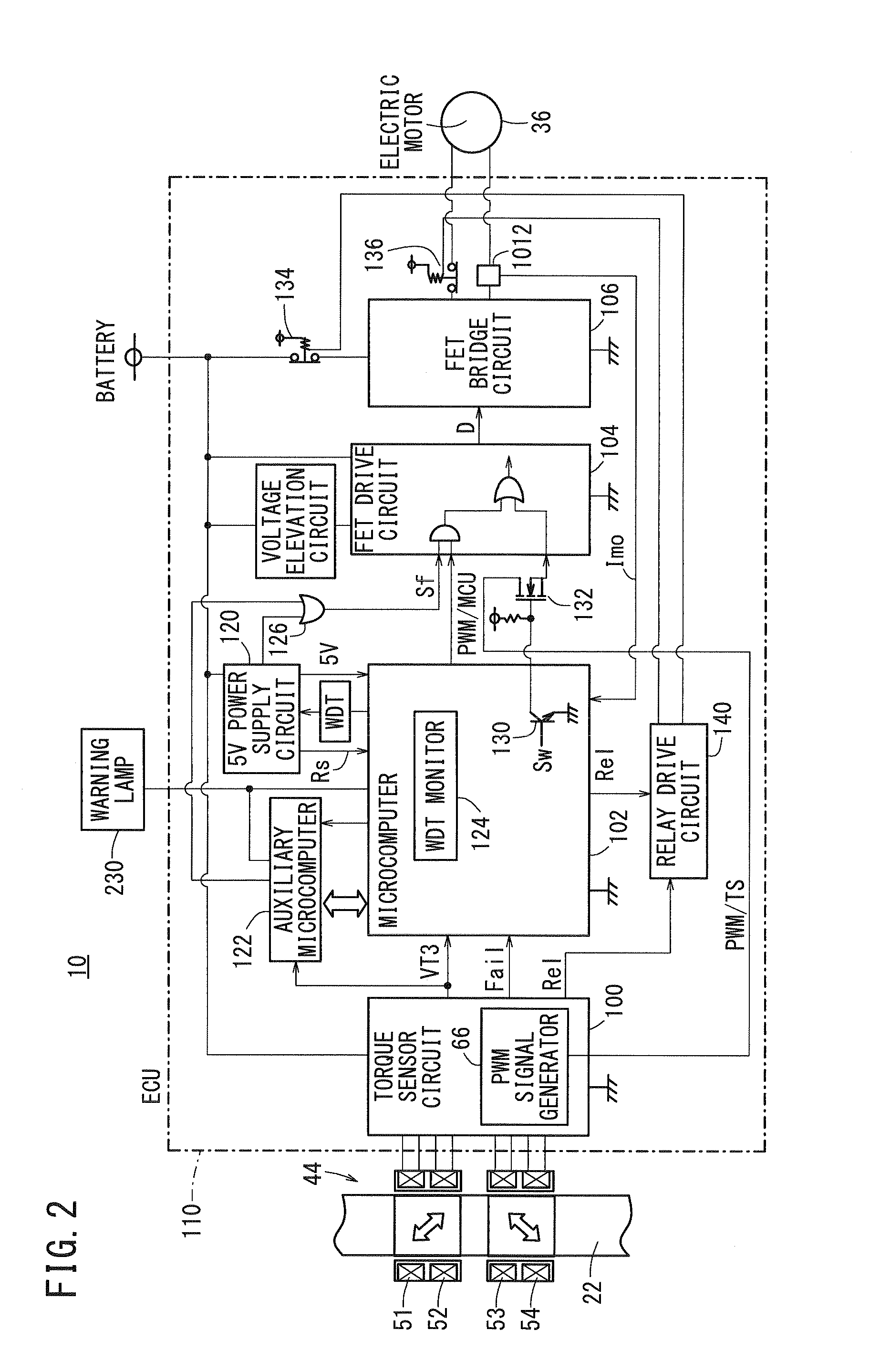
[0065]FIG. 1 schematically shows, partially in block form, an electric power steering apparatus (EPS) 10 according to a first embodiment of the present invention. FIG. 2 shows in block form a circuit arrangement of the electric power steering apparatus 10 according to the first embodiment. FIG. 3 shows in block form a torque sensor circuit 100 of the electric power steering apparatus 10.

[0066]As shown in FIG. 1, the electric power steering apparatus 10, which is incorporated in a vehicle, includes a steering shaft assembly 14 coupled to a steering wheel 12, which serves as a steering member. The steering shaft assembly 14 includes a main steering shaft 16 integrally connected to the steering wheel 12, and a pinion shaft 22 having a pinion gear 20 of a rack and pinion mechanism 18. The main steering shaft 16 and the pinion shaft 22 are coupled to each other by a pair of universal joints 24.

[0067]The pinion shaft 22 has an upper portion, an intermediate portion, and a lower portion, w...

2nd embodiment

[0139]FIG. 14 schematically shows, partially in block form, an electric power steering apparatus 10A according to a second embodiment of the present invention. FIG. 15 shows in block form a circuit arrangement of the electric power steering apparatus 10A according to the second embodiment.

[0140]Those parts shown in FIGS. 14 and 15, which correspond to or are identical to those shown in FIGS. 1 and 2, are denoted by corresponding or identical reference characters, and such features will not be described in detail below.

[0141]As shown in FIGS. 14 and 15, a torque sensor circuit 100 does not comprise part of, but is located outside of, an ECU 110A, which is integrally combined with the electric motor 36. The torque sensor circuit 100 is integrally combined with the assembly of the coils 51 through 54 of the magnetostrictive torque sensor 44, and is housed in a casing made of a PPS resin, which is a functional resin that is highly resistant to heat and fire, and has excellent electrical...

3rd embodiment

[0145]FIG. 16 shows in block diagram a circuit arrangement of an electric power steering apparatus 10B according to a third embodiment of the present invention.

[0146]Those parts shown in FIG. 16, which correspond to or are identical to those shown in FIGS. 2 and 15, are denoted by corresponding or identical reference characters, and such features will not be described in detail below.

[0147]As shown in FIG. 16, a PWM signal generator 66 for generating and outputting a PWM signal TS depending on the torque signal VT3 is located inside an ECU 110B, which is integrally combined with the electric motor 36. Accordingly, the number of components connected between a torque sensor circuit 100B, which is disposed outside the ECU 110B, and the ECU 110B is reduced.

[0148]As described above, each of the electric power steering apparatus 10, 10A, 10B according to the above-described embodiments includes the electric motor 36 for applying an assistive steering force to a steering system (i.e., the ...


PUM


Abstract

In the event of a failure of a first electric motor drive signal generator, e.g., the microcomputer, which generates a first electric motor drive signal for performing a feedback control, a second electric motor drive signal generator, e.g., a PWM signal generator, which is made up of discrete circuit components, directly converts a steering torque signal into a second electric motor drive signal. An electric motor, which generates the assistive steering force, is driven by the second electric motor drive signal.

Description

CROSS-REFERENCE TO RELATED APPLICATION[0001]This application is based upon and claims the benefit of priority from Japanese Patent Application No. 2011-095801 filed on Apr. 22, 2011, of which the contents are incorporated herein by reference.BACKGROUND OF THE INVENTION[0002]1. Field of the Invention[0003]The present invention relates to an electric power steering apparatus for transmitting power from an electric motor, which serves as an assistive steering force (steering assisting force), to a vehicle steering system in order to reduce the burden on a driver of a vehicle who operates a steering member such as a steering wheel when the driver turns the steering member to steer the vehicle.[0004]2. Description of the Related Art[0005]Recent years have seen widespread use of electric power steering apparatus, which detect a steering torque generated by the steering wheel of a vehicle with a steering torque sensor and energize an electric motor to generate an assistive steering force d...

Claims


Application Information

Patent Timeline
Patent Type & Authority Applications(United States)
IPC IPC(8): B62D6/10
CPCB62D5/0493B62D5/0484
Inventor YONEDA, ATSUHIKOSHIMIZU, YASUOONIWA, YOSHIHIROWAKAKUMA, YUKIHIROMIYOSHI, TAKASHI
Owner HONDA MOTOR CO LTD
Why Eureka
Try Eureka