Double-acting scotch yoke assembly for x-engines

Active Publication Date: 2012-11-01
DIGGS MATTHEW BYRNE
View PDF10 Cites 12 Cited by
  • Summary
  • Abstract
  • Description
  • Claims
  • Application Information

AI Technical Summary

Benefits of technology

[0006]An object of the invention is to provide a Double-Acting Scotch Yoke (DASY) mechanism for X-engines that, relative to conventional piston engines which use con

Problems solved by technology

Con rods, due to the nature of their motion, produce multiple orders of vibration such that there is no practical way to cancel out all of the resultant vibration in an engine that has con rods.
Some conventional e

Method used


Image

  • Double-acting scotch yoke assembly for x-engines
  • Double-acting scotch yoke assembly for x-engines
  • Double-acting scotch yoke assembly for x-engines

Examples


Embodiment Construction

[0025]Below are illustrations and explanations for a Double-Acting Scotch Yoke (DASY) assembly for an X-engine configuration. However, it is noted that the DASY assembly may be configured to suit any specific application and is not limited only to the example in the illustrations.

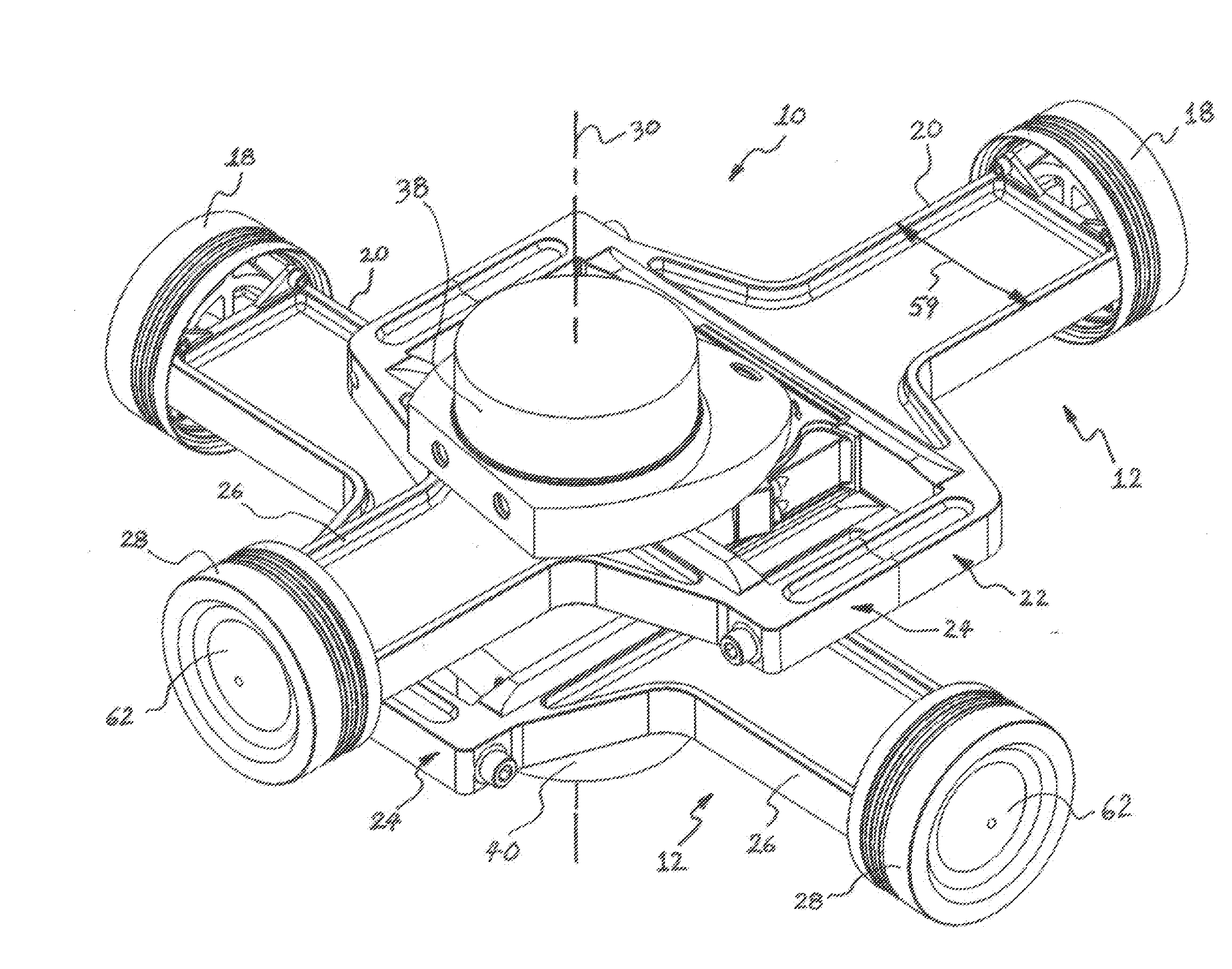
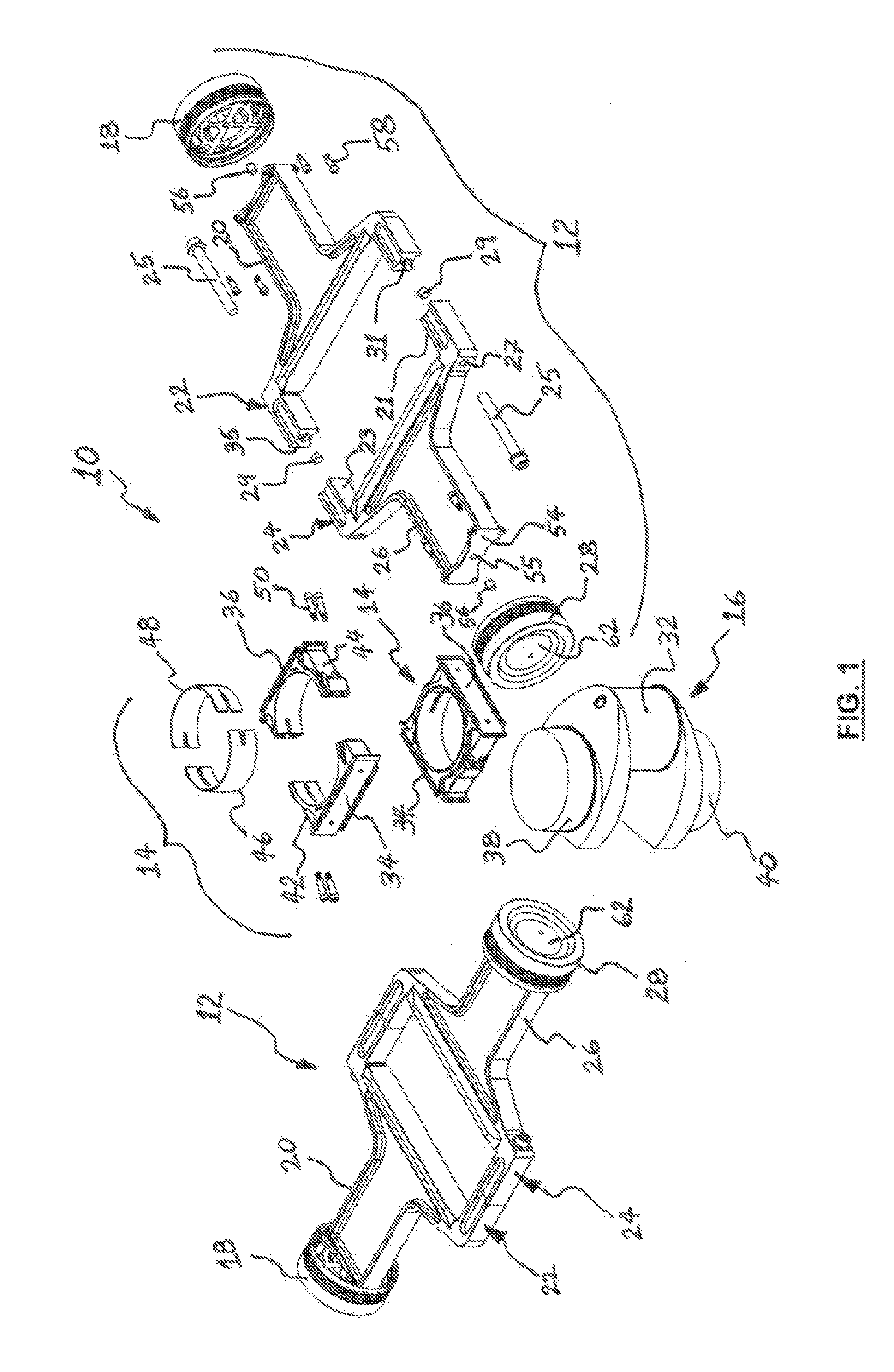
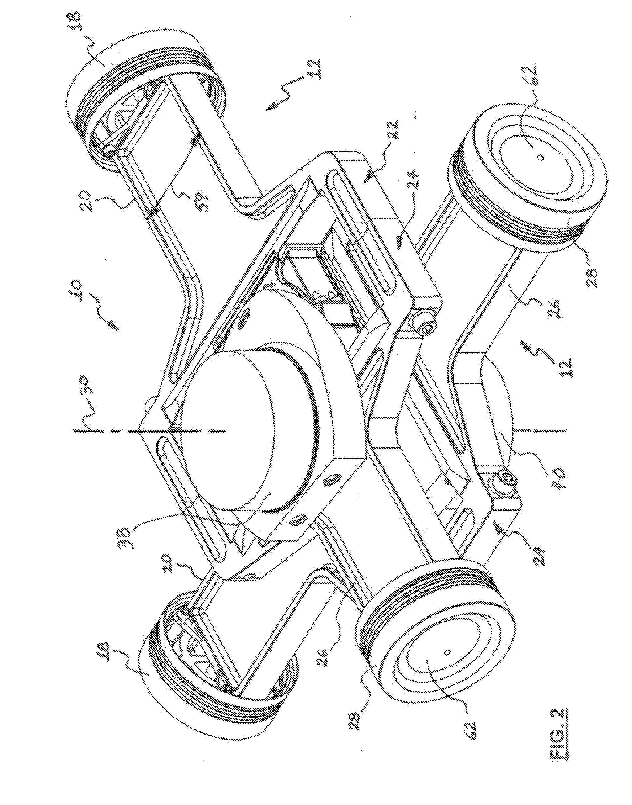
[0026]Referring now to FIGS. 1-4, a Double-Acting Scotch Yoke (DASY)

[0027]X-Engine crank train 10 is shown according to an embodiment of the invention. In general, the crank train 10 includes two DASY assemblies 12, two bearing block assemblies 14 and a crankshaft 16. In the illustrated embodiment, the X-engine crank train 10 is configured as a DASY X-4 crank train. However, it will be appreciated that the principles of the DASY assembly 12 of the invention can be applied to other X-engine crank trains, such as a X-8 engine crank train, a X-12 engine crank train, a X-16 engine crank train, and the like.

[0028]The DASY assembly 12 forms a basic building block of the DASY X-engine crank train 10 and comprises ...


PUM


Abstract

A Double-Acting Scotch Yoke (DASY) assembly includes a first yoke; a second yoke attached to the first yoke at a first flat-to-flat interface; a first piston attached to the first yoke at a second flat-to-flat interface; and a second, opposing piston attached to the second yoke at a third flat-to-flat interface. The planes of all of the flat-to-flat interfaces are perpendicular to a common, center axis of the first and second pistons. An X-engine crank train includes a plurality of DASY assemblies.

Description

BACKGROUND OF THE INVENTION[0001]The invention relates generally to internal combustion piston engines, fluid pumps and similar machines and, more particularly to a Double-Acting Scotch Assembly (DASY) for an X-Engine configuration.[0002]The most widely used engine configurations in use today are in-line, “V” and horizontally-opposed or ‘flat’. Almost all of these engines use conventional connecting rods (“con rods”) in the power conversion system. Con rods, due to the nature of their motion, produce multiple orders of vibration such that there is no practical way to cancel out all of the resultant vibration in an engine that has con rods. Some conventional engine configurations which use con rods, such as the 90° V-8, have balance for 1st-order and 2nd-order vibrations, but practically all engines with conventional con rods are never balanced for 3rd-orders and above.[0003]The Scotch yoke is a mechanism for converting the linear motion of a slider into rotational motion or vice-ver...

Claims


Application Information

Patent Timeline
IPC IPC(8): F16H21/34
CPCF01B9/023F02B75/222F02B75/227F02B75/246Y10T74/18256F02B41/04F02B75/048F02B75/32F02B2075/025F02B3/06
Inventor DIGGS, MATTHEW BYRNE
Owner DIGGS MATTHEW BYRNE
Why Eureka
Try Eureka