
Method for fabricating hole pattern in semiconductor device

a semiconductor device and hole pattern technology, applied in the direction of capacitors, electrical appliances, basic electric elements, etc., can solve the problems of difficult to reduce the size of a semiconductor chip, difficult to perform patterning using photoresist, and high equipment costs, so as to achieve the effect of securing a process margin and simplifying the patterning process

Inactive Publication Date: 2012-11-01
SK HYNIX INC
View PDF5 Cites 5 Cited by
  • Summary
  • Abstract
  • Description
  • Claims
  • Application Information

AI Technical Summary

Benefits of technology

[0011]Another embodiment of the present invention is directed to a method for fabricating a hole pattern in a semiconductor device, which is capable of simplifying a patterning process and securing a process margin.

Problems solved by technology

In sub-30 nm devices, for example, it is difficult to perform patterning using photoresist due to limitations in the resolution of exposure equipment.
So far, it has been difficult to reduce the size of a semiconductor chip.
For example, while extreme ultraviolet (EUV) exposure technology may be used, equipment is expensive and is still in the initial developing stages, where it is difficult to be commercialized.

Method used


Image

  • Method for fabricating hole pattern in semiconductor device
  • Method for fabricating hole pattern in semiconductor device
  • Method for fabricating hole pattern in semiconductor device

Examples


first embodiment

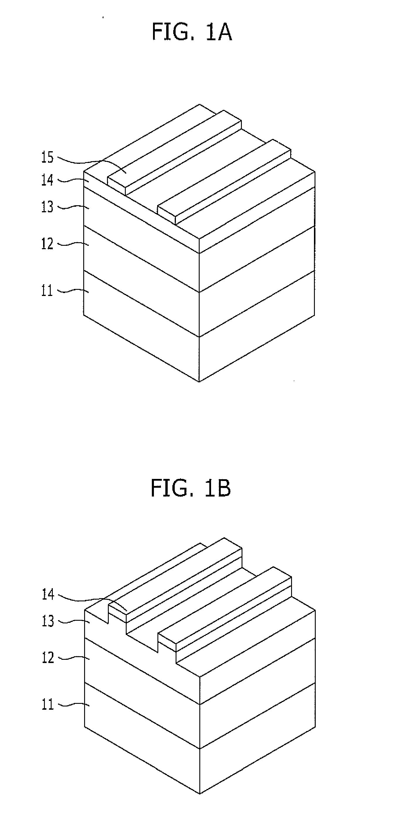
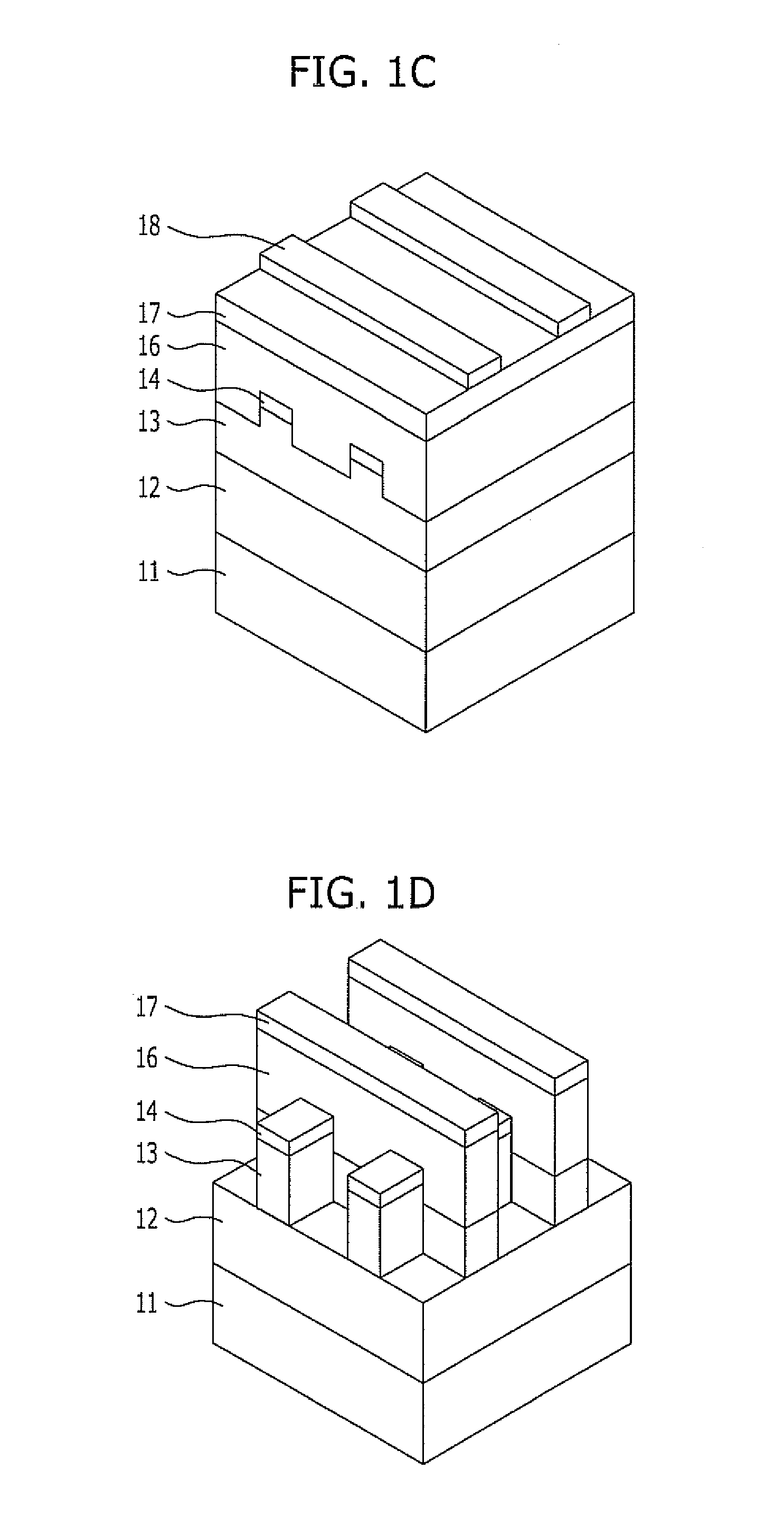
[0018]FIGS. 1A to 1F are cross-sectional views illustrating a method for fabricating a hole pattern in a semiconductor device in accordance with a first embodiment of the present invention.

[0019]Referring to FIG. 1A, a hard mask layer 12, a first organic layer 13, and a first inorganic layer 14 are stacked over a layer 11 which is to be etched (hereinafter, referred to as an etch layer 11). The etch layer 11 may include a mold layer for forming a storage node and may be formed of oxide or polysilicon.

[0020]The hard mask layer 12 serves as an etch barrier for etching the etch layer 11. When the etch layer 11 is formed of oxide, the hard mask layer 12 may be formed of polysilicon, and when the etch layer 11 is formed of polysilicon, the hard mask layer 12 may be formed of oxide.

[0021]The first organic layer 13 is formed of carbon and may include an amorphous carbon layer. The first inorganic layer 14 serves as an etch barrier of the first organic layer 13 and serves to prevent reflect...

second embodiment

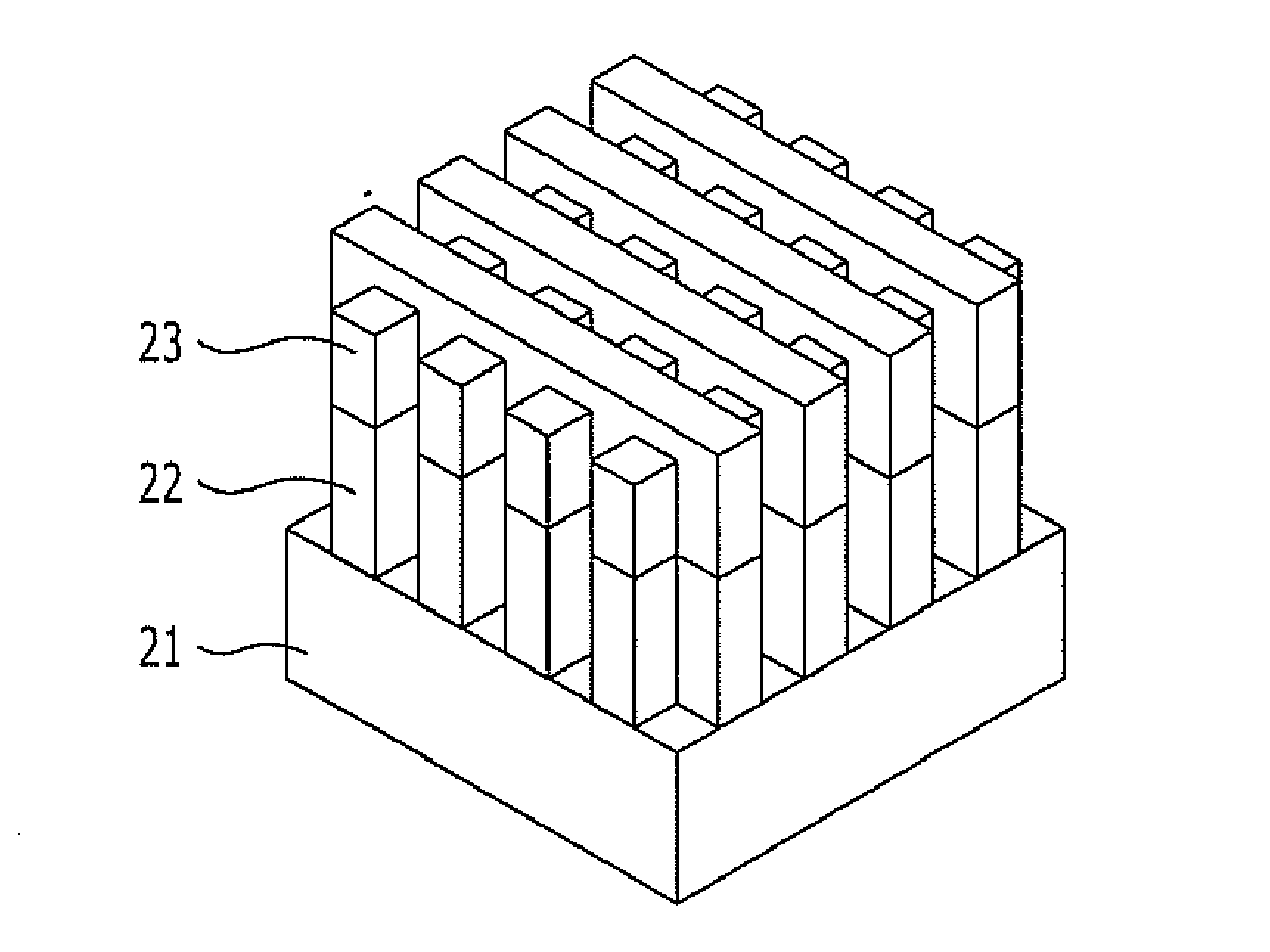
[0037]FIGS. 2A to 2K are cross-sectional views illustrating a method for fabricating a hole pattern in a semiconductor device in accordance with a second embodiment of the present invention.

[0038]Referring to FIG. 2A, a hard mask layer 22, a first organic layer 23, and a first inorganic layer 24 are stacked over an etch layer 21. The etch layer 21 may include a mold layer for forming a storage node and may be formed of oxide or polysilicon.

[0039]The hard mask layer 22 serves as an etch barrier for etching the etch layer 21. When the etch layer 21 is formed of oxide, the hard mask layer 22 may be formed of polysilicon, and when the etch layer 21 is formed of polysilicon, the hard mask layer 22 may be formed of oxide.

[0040]The first organic layer 23 is formed of carbon and may include an amorphous carbon layer. The first inorganic layer 24 serves as an etch barrier of the first organic layer 23 and serves to prevent reflection when a photoresist pattern is formed. The first inorganic ...


PUM


Abstract

A method for fabricating a hole pattern in a semiconductor device includes forming a first organic layer over an etch layer, forming a first inorganic layer pattern over the first organic layer, etching the first organic layer using the first inorganic layer pattern as an etching barrier, forming a second organic layer over the first organic layer, forming a second inorganic layer pattern over the second organic layer, where the second inorganic layer pattern crosses the first inorganic pattern, etching the first and second organic layers using the second inorganic layer pattern as an etching barrier, and etching the etch layer using the etched first and second organic layers as an etch barrier to form a hole pattern.

Description

CROSS-REFERENCE TO RELATED APPLICATIONS[0001]The present application claims priority of Korean Patent Application No. 10-2011-0041042, filed on Apr. 29, 2011, which is incorporated herein by reference in its entirety.BACKGROUND[0002]1. Field[0003]Exemplary embodiments of the present invention relate to semiconductor fabrication technology, and more particularly, to a method for fabricating a hole pattern in a semiconductor device.[0004]2. Description of the Related Art[0005]With the increase in integration degree of devices, the critical dimension (CD) of a pattern decreases. In sub-30 nm devices, for example, it is difficult to perform patterning using photoresist due to limitations in the resolution of exposure equipment.[0006]Accordingly, a method of reducing the diameter of a contact hole through a reflow or RELACS (resolution enhancement lithography assisted by chemical shrink) process of photoresist has been proposed.[0007]In the reflow process of photoresist, a contact hole p...

Claims


Application Information

Patent Timeline
Patent Type & Authority Applications(United States)
IPC IPC(8): H01L21/311
CPCH01L21/0337H01L28/92H01L21/32139H01L21/31144H01L21/0274H01L21/32055
Inventor JUNG, JIN-KIPARK, JUNG-HEE
Owner SK HYNIX INC
Learn More