Method for patterning a surface of a substrate

Pending Publication Date: 2022-03-10
INL INT IBERIAN NANOTECHNOLOGY LAB
View PDF0 Cites 0 Cited by
  • Summary
  • Abstract
  • Description
  • Claims
  • Application Information

AI Technical Summary

Benefits of technology

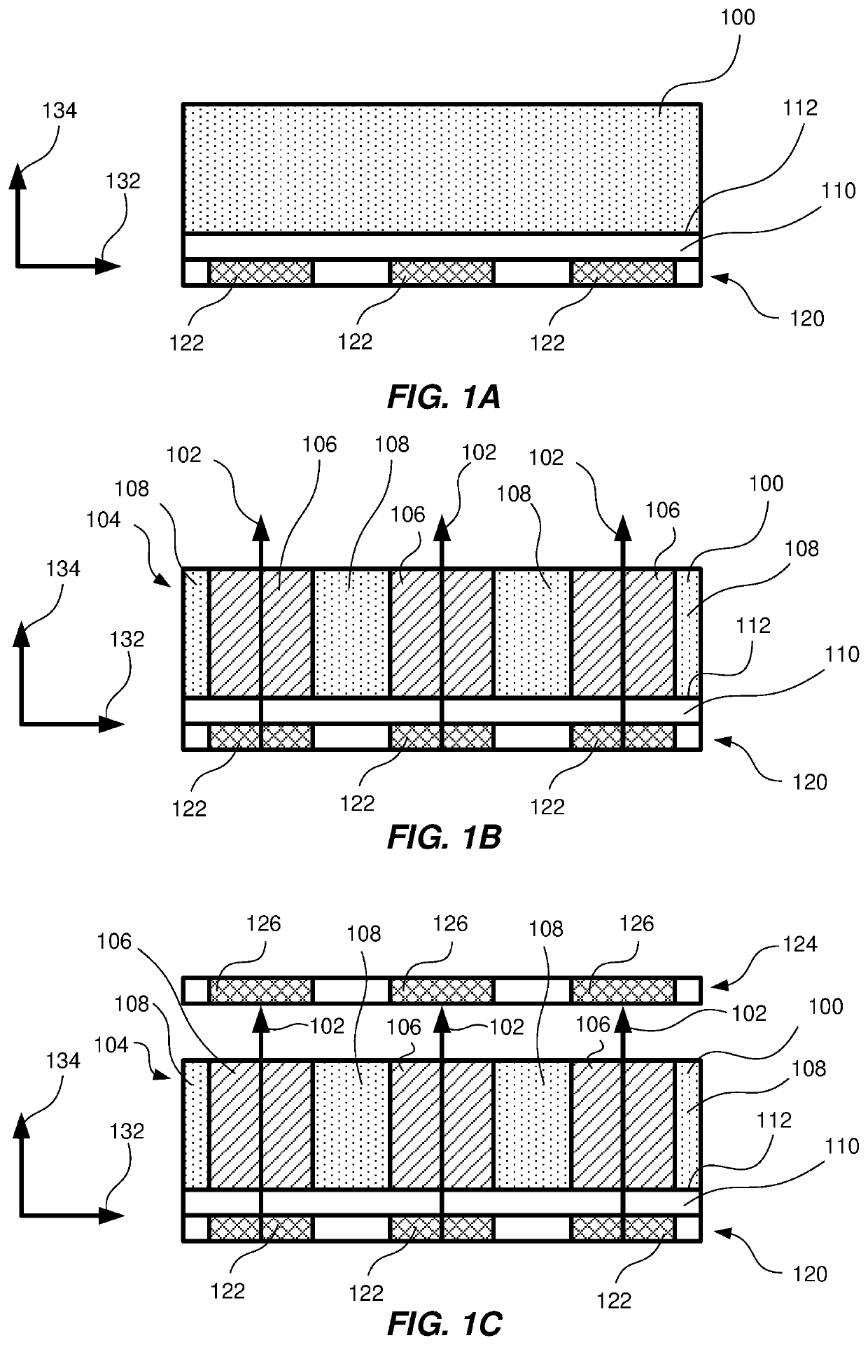
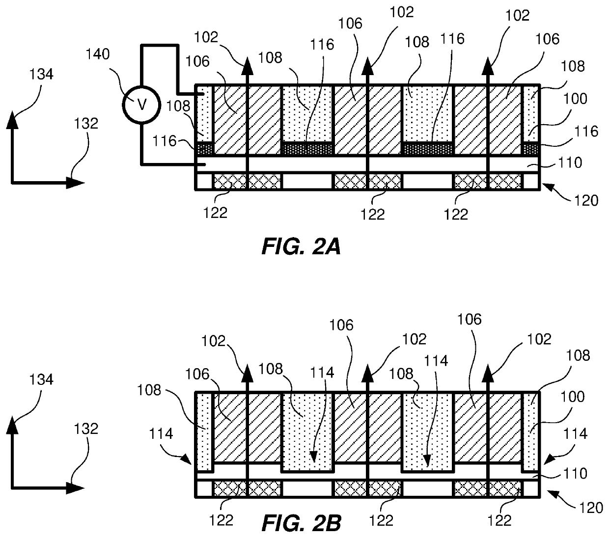
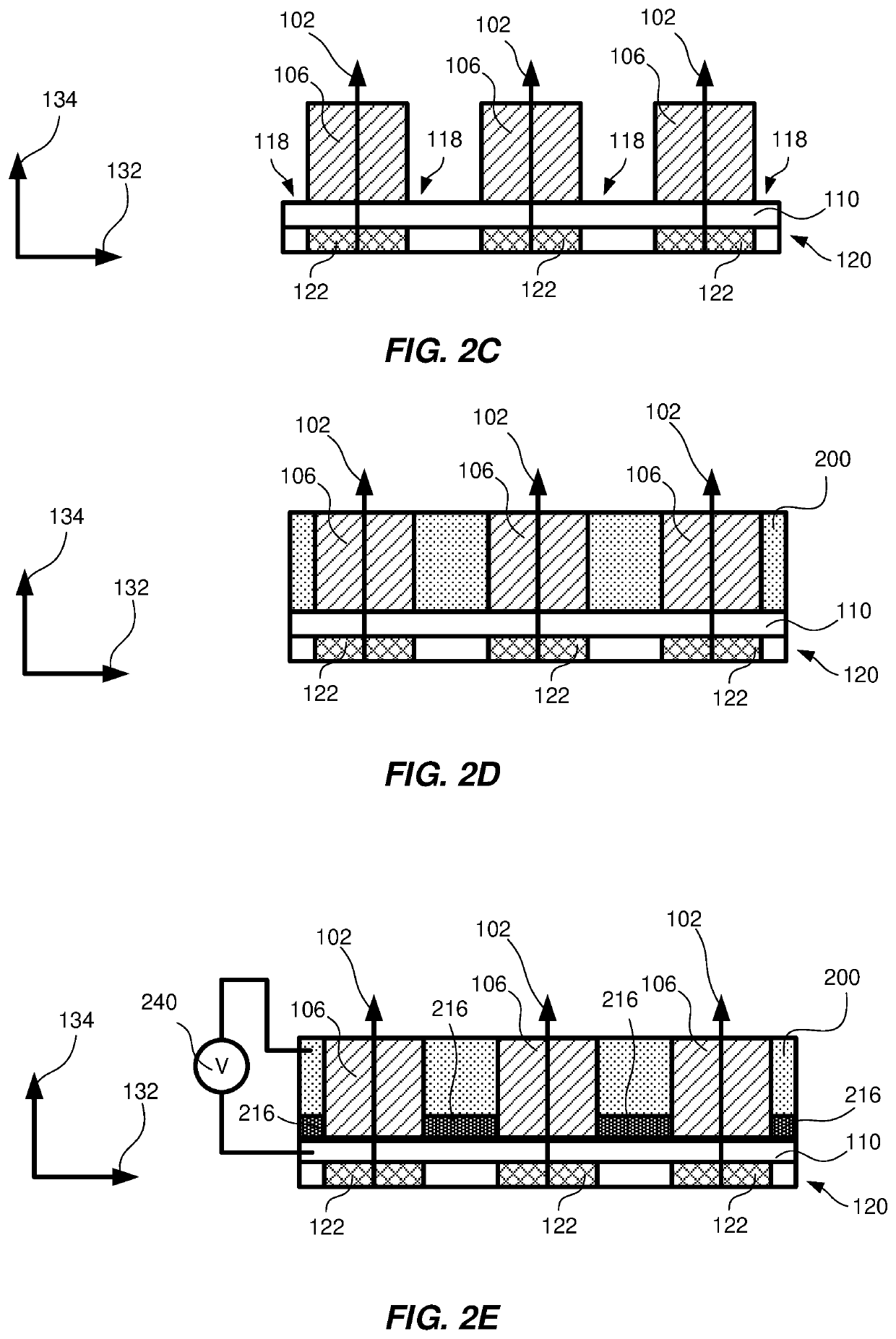
[0033]An advantage of applying a deposition magnetic field in the liquid, thereby depositing material species present in the liquid on the surface of the substrate is that the liquid forming the mask may be used in the surface modifying process. Thereby, the process of patterning a surface may be simplified as a need for a different liquid in the surface modifying process is removed. The material species deposited on the surface of the substrate may be fixated by a hardening process. The hardening process may be a chemical hardening process, and/or a heat-treatment process. The heat-treatment process may be a firing process. In other words, the material species may be bound together as well as to the surface of the substrate, thereby forming a stable deposited layer on the surface of the substrate.
[0034]The method may further comprise: subsequent to patterning the surface of the substrate, removing the applied field, thereby diminishing the spatially varied apparent viscosity distribution in the liquid.
[0035]An advantage of diminishing the spatially varied apparent viscosity distribution in the liquid is that the mask may be removed by removing the liquid. Thereby, the mas

Problems solved by technology

Problems associated with this process are many.
For instance, the additional sacrificial layer applied to the substrate leads to additional processing steps, which in turn decreases production rates.
It is also problematic to imprint the inverse of the pattern on the sacrificial layer, since it typically requires very expensive equipment, e.g. photolithography equipment.
Another common issue is that after the expo

Method used


Image

  • Method for patterning a surface of a substrate
  • Method for patterning a surface of a substrate
  • Method for patterning a surface of a substrate

Examples


example 1

ckening Magnetorheological Liquid

[0113]All concentrations (volumetric, molar, wt. %, etc.) given in this example are in relation to the complete (i.e. comprising all constituents) liquid. The liquid may be diluted with water in order to achieve the desired concentrations.

[0114]In this first example, a shear-thickening magnetorheological liquid is used in a process where metallic nickel is deposited on a non-conducting plastic substrate. The surface of the plastic substrate was pretreated (e.g., by plasma or corona treatment) such that it can be plated. The shear-thickening additive of the magnetorheological liquid in this example is hexadecyltrimethylammonium bromide at a concentration of 0.3 M and p-toluene sulfonate at a concentration of 0.5 M in water. The magnetic additive of the magnetorheological liquid in this example is silica-coated iron microparticles at a concentration of 15 wt. % and silica-coated disordered chromium nanoparticles at a concentration of 20 wt. %. Ammonia ...

example 2

nning Magnetorheological Liquid

[0118]All concentrations (volumetric, molar, wt. %, etc.) given in this example are in relation to the complete (i.e. comprising all constituents) liquid. The liquid may be diluted with water in order to achieve the desired concentrations.

[0119]In this second example, a shear-thinning magnetorheological liquid is used in a process where CdTe films are deposited on a conducting aluminum foil. The shear-thinning additive of the magnetorheological liquid in this example is xanthan gum powder at a concentration of 5 gram per liter. The magnetic additive of the magnetorheological liquid in this example is silica-coated iron microparticles at a concentration of 1 wt. % and silica-coated disordered chromium nanoparticles at a concentration of 5 wt. %.

[0120]The concentrations given above are to be seen as examples only, it has been found that they may be varied. For example, in the shear-thinning magnetorheological liquid, the concentration of xanthan gum powd...

example 3

ckening Electrorheological Liquid

[0123]All concentrations, unless explicitly stated otherwise, (volumetric, molar, wt. %, etc.) given in this example are in relation to the complete (i.e. comprising all constituents) liquid. The liquid may be diluted with silicone oil in order to achieve the desired concentrations.

[0124]In this third example, a shear-thickening electrorheological liquid is used in a process where Mo is etched from a Mo-coated silicon wafer.

[0125]The shear-thickening additive of the electrorheological liquid in this example is silica nanoparticles at a concentration of 10 wt. % in silicone oil, whereby wt. % here is with respect to the silicone oil. The electrorheological additive of the electrorheological liquid in this example is barium titanyl oxalate [BaTiO(C2O4)2] nanoparticles (concentration of 20 volumetric %) coated with urea.

[0126]The concentrations given above are to be seen as examples only, it has been found that they may be varied. For example, in the sh...


PUM


Abstract

A method for patterning a surface of a substrate includes applying a liquid on the surface of the substrate, wherein an apparent viscosity of the liquid depends on a field strength applied to the liquid; applying a field to the liquid, wherein a field strength of the applied field is spatially varied in the liquid in a direction parallel to the surface of the substrate, thereby generating a spatially varied apparent viscosity distribution in the liquid in response to the applied field; and patterning the surface of the substrate by subjecting the surface to a surface modifying process, while maintaining the field and using portions of the liquid having apparent viscosities higher than a predetermined value as a mask; wherein the surface modifying process comprises removing material of the surface of the substrate and/or depositing material on the surface of the substrate.

Description

TECHNICAL FIELD[0001]The present invention relates to a method for patterning a surface of a substrate.BACKGROUND OF THE INVENTION[0002]The production of patterned surfaces is important in a range of different technical areas. For instance, in the production of semiconductor components such as solar panels and optical displays. A patterned surface is typically produced by transferring a pattern from a template to a target substrate, such as a wafer. The transfer can be performed by applying a sacrificial layer on top of the substrate, and then imprint an inverse of the pattern on the sacrificial layer. The patterned sacrificial layer is typically called a mask. The exposed parts of the substrate can then be etched or be deposited with material.[0003]Problems associated with this process are many. For instance, the additional sacrificial layer applied to the substrate leads to additional processing steps, which in turn decreases production rates. It is also problematic to imprint the...

Claims


Application Information

Patent Timeline
IPC IPC(8): H01L21/033H01L21/311H01L21/32
CPCH01L21/0337H01L21/32H01L21/31144
Inventor COLOMBARA, DIEGO
Owner INL INT IBERIAN NANOTECHNOLOGY LAB
Why Eureka
Try Eureka