Eureka AIR delivers breakthrough ideas for toughest innovation challenges, trusted by R&D personnel around the world.

System and Method for Determining Fluid Flow of Compressible and Non-Compressible Liquids

Active Publication Date: 2012-11-01
UNIVERSITY OF WINDSOR
View PDF3 Cites 3 Cited by
  • Summary
  • Abstract
  • Description
  • Claims
  • Application Information

AI Technical Summary

Benefits of technology

[0011]Furthermore, another object of this invention to provide a better method and system for computing the fluid dynamics of non-compressible liquids within a pipe or transport mechanism, the pipe or transport mechanism having certain boundary conditions.
[0012]The inventors have appreciated that if the solution domain can be discretized into a smooth structured grid, the FDM is better than the FVM (or the FEM) due to its efficiency. In particular, an FDM method requires less memory and has better stability. Furthermore, a system and method relying on an FDM has better convergence properties.
[0014]In one cell-centered finite different approach described hereafter lies in the discovery and development of a unified scheme for the numerical solution of Partial Differential Equations (PDEs), irrespective of their physical origin, which is solely based on the finite difference method, but is implemented in an innovative fashion that allows the use of an arbitrary mesh topology. Thus, the CCFDM enjoys the simplicity and strength of the traditional FDM, and the power and flexibility of the FVM and FEM.
[0015]The resulting program may evolve into entirely new multiphysics computational continuum mechanics software, or replace the core numerical processing component of some existing software packages with a much simpler and more efficient algorithm which permits a natural and seamless coupling of fluid and solid interaction, allows for a more precise analysis of accuracy and produces faster, more accurate and more reliable results.

Problems solved by technology
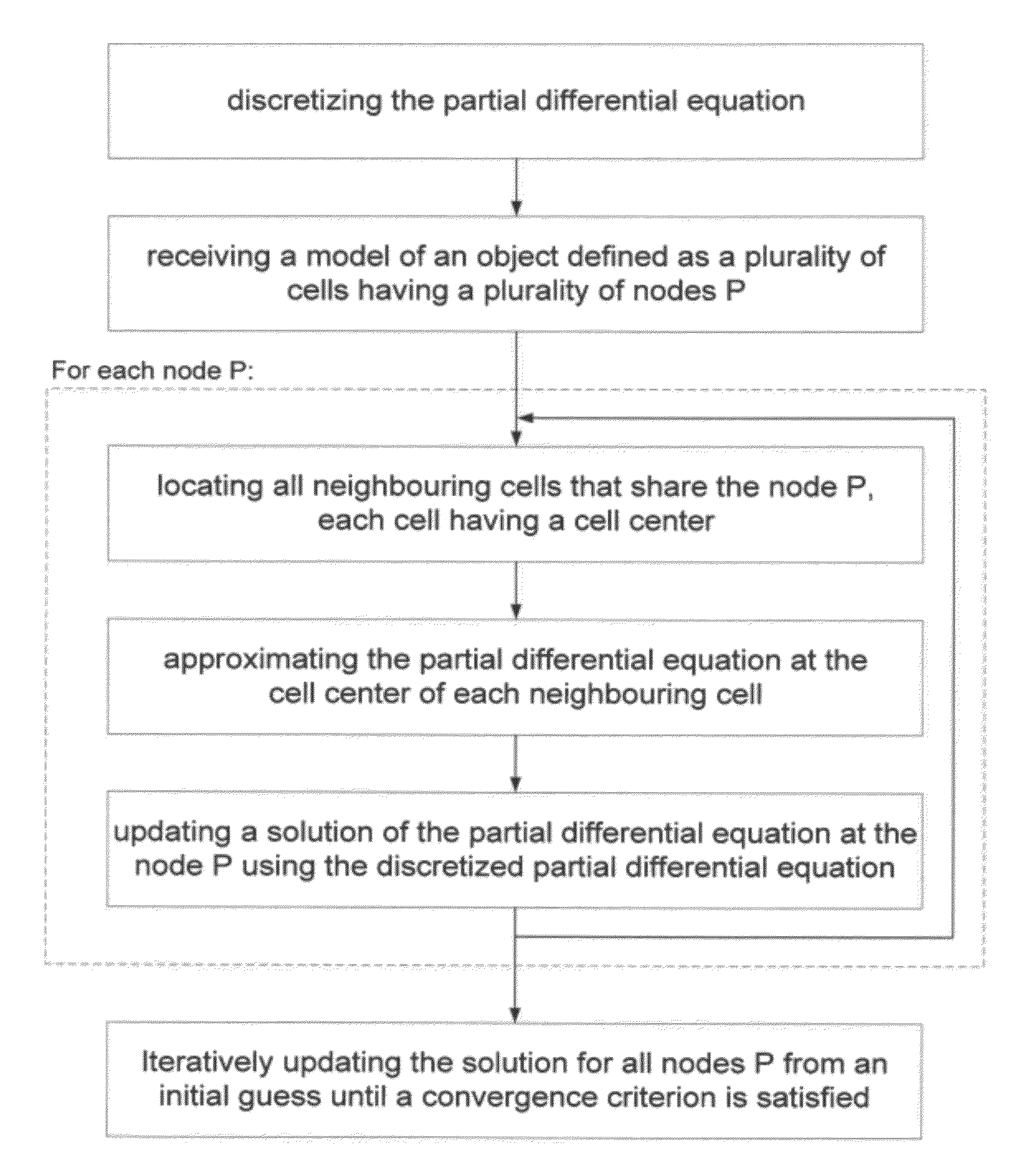
In addition, there may be a need to use a multiblock scheme if the physical domain is too complicated.
Traditional Finite Difference Methodology is typically difficult to deal with in complicated grid arrangements.
Even with coordinate transformations, highly irregular domains may create serious difficulties for accuracy and convergence due to numerical discontinuities in the transformation metrics.
With CCFVM / VCFVM, inaccuracies due to calculation of fluxes across cell faces may be difficult to deal with.
In addition, there are difficulties associated with treatment near boundaries for higher-order schemes, and accuracy and convergence issues associated with cells that are severely skewed or have a high aspect ratio.
Accordingly, current computer modelling schemes are limited in the form of objects they can model and require different models and algorithms for different fluid applications, such as between compressible and non-compressible fluids.

Method used


Image

  • System and Method for Determining Fluid Flow of Compressible and Non-Compressible Liquids
  • System and Method for Determining Fluid Flow of Compressible and Non-Compressible Liquids
  • System and Method for Determining Fluid Flow of Compressible and Non-Compressible Liquids

Examples


embodiment # 1

Embodiment #1

Compressible Fluids

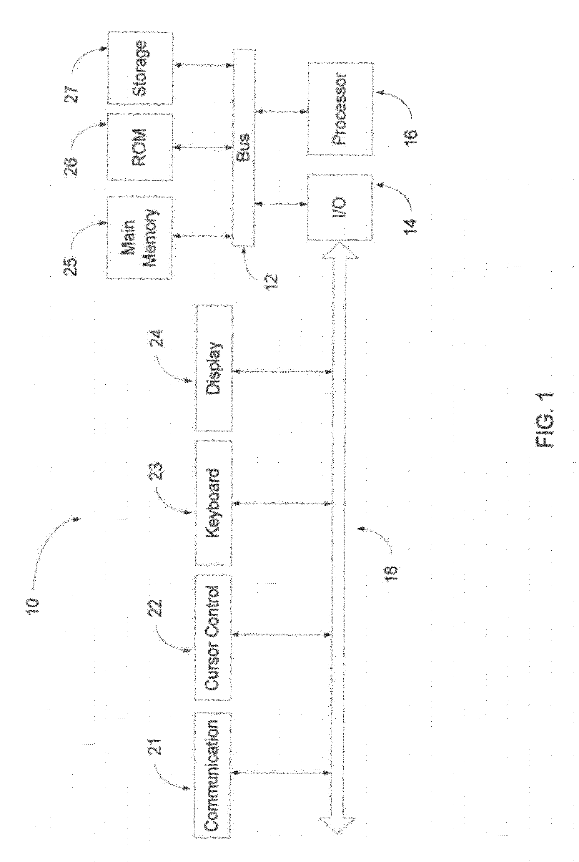
[0042]In a preferred embodiment, computer system 10 is used in conjunction with to model the fluid dynamics of an aircraft landing gear through the air, such as during aircraft landing and in flight. In use of the system 10, a computer-aided designed (CAD) representation of the aircraft landing gear and supporting structure is inserted into the model.

[0043]Airflow, as a compressible fluid, may be constrained by initial conditions entered as part of the model or taken from sensors from real-world applications. The airflow may be modeled as a partial differential equation, as known in the art of fluid dynamics. For example, data from temperature and speed sensors may be included in the model, taken from real-world applications.

[0044]Once the boundary conditions and initial conditions have been inputted, the profile is input into the system 10 of the present invention and when the solution converges to a steady state, the solution is outputted. The solut...

embodiment # 2

Embodiment #2

Non-Compressible Fluids

[0047]The above-described computer system 10 can also be used to model the fluid dynamics of a non-compressible fluid through a defined space. For example, in a preferred embodiment, the computer system 10 can model a fluid such as water through a pipe or other transport mechanism.

[0048]As with the compressible embodiment, described above, a computer-aided designed (CAD) representation of the pipe is inserted into the simulation. Typical boundary conditions may be represented in the model.

[0049]The system 10 then models the flow of the non-compressible fluid, i.e. water or gas, through the pipe in successive stages. The non-compressible fluid may be further defined by its initial conditions or parameters. For example, the non-compressible fluid may include particulate matter and have a specific viscosity. The non-compressible fluid may be constrained by initial conditions entered as part of the computer simulation or taken from sensors from real-w...

examples

[0087]FIGS. 7A to 7D, 8A, 8B and 9A to 9C illustrate graphically first example test cases with uniform structured mesh, clustered structured mesh, unstructured triangulated mesh, and unstructured refined mesh, as well as comparisons between the CCFDM solution, FEM and exact solutions.

[0088]In FIGS. 7A to 7D, a sample test case using the Laplace equation on a unit square with Dirichlet boundary conditions is illustrated. The Laplace equation for the sample test is described according to the following equations:

∂2T∂x2+∂2T∂y2=0;∀(x,y)∈(0,0)×(1,1)T(x,0)=T(x,1)=T(1,y)=0,T(0,y)=1

[0089]Different meshes are shown for the unit square. In FIG. 7A, a uniform structured mesh is shown. In FIG. 7B, a clustered structured mesh is shown. In FIG. 7C, an unstructured (triangulated) mesh is shown. In FIG. 7D, an unstructured refined mesh is shown.

[0090]FIG. 8A shows the CCFDM solution to the sample test case using the Laplace equation on a unit square, in accordance with an embodiment of the present i...


PUM


Abstract

A system and method for determining fluid flow of compressible and non-compressible liquids is described. The system may include input means for receiving a model of an object defined as a plurality of cells having a plurality of nodes P, and a processor coupled to a memory. The processor may be configured for: discretizing a partial differential equation (PDE) corresponding to the received model; for each node P: (i) locating all neighbouring cells that share the node P, each of the neighbouring cells having a cell center; (ii) approximating the PDE at the cell center of the neighbouring cells using the discretized PDE; and (iii) updating a solution of the PDE at the node P by using the approximated discretized PDE at all the neighbouring cell centers; and iteratively updating the solution for all the nodes P from an initial guess until a convergence criterion is satisfied.

Description

RELATED APPLICATIONS[0001]This application claims the benefit under 35 USC §119(e) to U.S. Provisional Application No. 61 / 457,589, filed on Apr. 26, 2011, the contents of which are hereby incorporated by reference in their entirety.FIELD OF THE INVENTION[0002]This invention relates to a system and method for modelling internal and / or boundary conditions, as for example to model or determine fluid flows in, around and / or across objects or structures and, in particular, for both compressible and non-compressible liquids.BACKGROUND OF THE INVENTION[0003]Computer methods and algorithms can be used to analyze and solve complex systems involving various forms of fluid dynamics having inputted boundary conditions. For example, computer modelling may allow a user to simulate the flow of air and other gases over an object or model the flow of fluid through a pipe. Computational fluid dynamics (CFD) is often used with high-speed computers to simulate the interaction of one or more fluids over...

Claims


Application Information

Patent Timeline
IPC IPC(8): G06F17/13
CPCG06F30/23G06F2111/10G06F17/17
Inventor BARRON, RONALDSALIH, ALISITU, JAMES JIANMIN
Owner UNIVERSITY OF WINDSOR
Why Eureka
Eureka Blog
Learn More