Lighting device for solid-state light source and illumination apparatus using same

Active Publication Date: 2012-11-15
PANASONIC CORP
View PDF5 Cites 83 Cited by
  • Summary
  • Abstract
  • Description
  • Claims
  • Application Information

AI Technical Summary

Benefits of technology

[0019]In accordance with the present invention, since changing the current flowing through the solid-state light source causes the frequency of the second switching control to vary, the flickering of light is not visible even if the current flowing thr

Problems solved by technology

In contrast, if the frequency for the low-frequency PWM control is set to be lower according to the case where the peak current is high,

Method used


Image

  • Lighting device for solid-state light source and illumination apparatus using same
  • Lighting device for solid-state light source and illumination apparatus using same
  • Lighting device for solid-state light source and illumination apparatus using same

Examples


embodiment 1

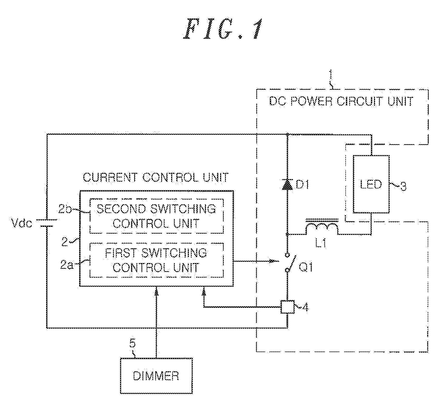
[0038]FIG. 1 is a circuit diagram of a lighting device for a solid-state light source in accordance with a first embodiment of the present invention. The lighting device includes an input DC power source Vdc, a DC power circuit unit 1 and a current control unit 2. The lighting device configures an illumination apparatus. The DC power circuit unit 1 is connected to the input DC power source Vdc. The DC power circuit unit 1 includes a recovery diode D1, an inductor L1, a switching element Q1 and a current detection unit 4. The DC power circuit unit 1 is a switching power supply circuit for converting the power of the input DC power source Vdc by using the switching element Q1, and supplying a DC current to a solid-state light source 3, such as an LED (or an OLED (Organic Light Emitting Diode)). Herein, a buck chopper circuit (buck converter) is used as the DC power circuit unit 1.

[0039]The configuration of the buck chopper circuit is well known, and is configured such that a series ci...

embodiment 2

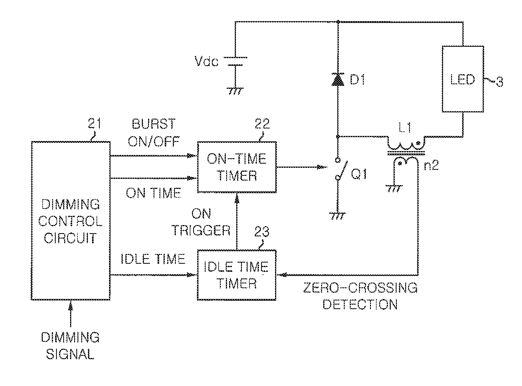
[0060]FIG. 4 is a circuit diagram of a lighting device for a solids state light source in accordance with a second embodiment of the present invention. The principal configuration of the circuit is similar to that of FIG. 1. In the present embodiment, a current control unit can be operated even in discontinuous mode shown in FIG. 5, in addition to critical mode shown in FIGS. 2A to 2C. The current control unit includes an ON-time timer 22 for setting an ON time shown in FIG. 5, an idle time timer 23 for setting an idle time shown in FIG. 5, and a dimming control circuit 21 for assigning control signals to the timers. The dimming control circuit 21 assigns a burst ON / OFF control signal, required to intermittently stop the operation of the ON-time timer 22 at a low frequency, to the ON-time timer 22 while instructing the ON time of the ON-time timer 22 and the idle time of the idle time timer 23 in response to a dimming signal from the dimmer.

[0061]Hereinafter, a control in which the ...

embodiment 3

[0070]FIG. 7 is a circuit diagram of a lighting device for a solids state light source in accordance with a third embodiment of the present invention. The principal configuration of the circuit is identical to that of FIG. 1. In the present embodiment, an oscillation cycle timer 24 instead of the idle time timer 23 in FIG. 4 is provided. The oscillation cycle timer 24 defines the shortest oscillation cycle, i.e., the highest frequency.

[0071]As shown in FIG. 7, the oscillation cycle timer 24 monitors the output of an ON-time timer 22, and then it generates a pulse voltage of a predetermined time period when the rising edge of the output from the ON-time timer 22 (i.e., timing at which a switching element Q1 is turned on) is detected. This pulse voltage is inputted to a trigger terminal of the ON-time timer 22 via a diode D4. Further, a flyback voltage outputted from the secondary coil n2 of an inductor L1 is inputted to the trigger terminal via a diode D3. The diodes D3 and D4 form a...


PUM


Abstract

A lighting device for lighting a solid-state light source includes: a DC power circuit unit for converting a power of an input DC power source using a switching element and flowing a current through a solid-state light source; and a control unit for performing a first switching control in which the switching element is turned on/off at a first high frequency and a second switching control in which an ON/OFF operation of the switching element is intermittently stopped at a second frequency lower than the first frequency of the first switching control. When the current flowing through the solid-state light source is changed, the second frequency is varied.

Description

FIELD OF THE INVENTION[0001]The present invention relates to a lighting device for lighting a solid-state light source, such as an LED (Light Emitting Diode), and to an illumination apparatus using the lighting device.BACKGROUND OF THE INVENTION[0002]As a prior art, Japanese Patent Application Publication No. 2006-511078 (JP2006-511078A) discloses a power supply assembly for an LED illumination module that performs dimming control on an LED by combining low-frequency PWM (Pulse Width Modulation) control with a high-frequency PWM control. This device includes a switch mode converter for supplying a constant current to the LED illumination module, and a dual PWM signal composed of low frequency bursts of high frequency pulses is provided to the control switch of the switch mode converter. By varying the average current flowing through the LED illumination module as the low-frequency component of the dual PWM signal is varied, the intensity of a light outputted from the LED illuminatio...

Claims


Application Information

Patent Timeline
IPC IPC(8): H05B37/02H05B44/00
CPCH05B33/0815H05B33/0848H05B33/0818H05B45/14H05B45/327H05B45/375H05B45/3725H05B45/38H05B45/385H05B45/39
Inventor WATANABE, KOJIMIZUKAWA, HIROMITSU
Owner PANASONIC CORP
Why Eureka
Try Eureka