Vibrothermographic Weld Inspections

Active Publication Date: 2012-11-15
AREVA NP SAS
View PDF7 Cites 12 Cited by
  • Summary
  • Abstract
  • Description
  • Claims
  • Application Information

AI Technical Summary

Benefits of technology

[0010]The present invention is related to a system and method of inspecting the J-groove welds of a nuclear reactor vessel head or BMN using vibrothermography. The weld to be inspected is subjected to a transient sonic excitation while the weld area is monitored using a remote infrared camera. The sonic excitation induces mechanical vib

Problems solved by technology

The sonic excitation induces mechanical vibration, wh

Method used


Image

  • Vibrothermographic Weld Inspections
  • Vibrothermographic Weld Inspections
  • Vibrothermographic Weld Inspections

Examples


Example

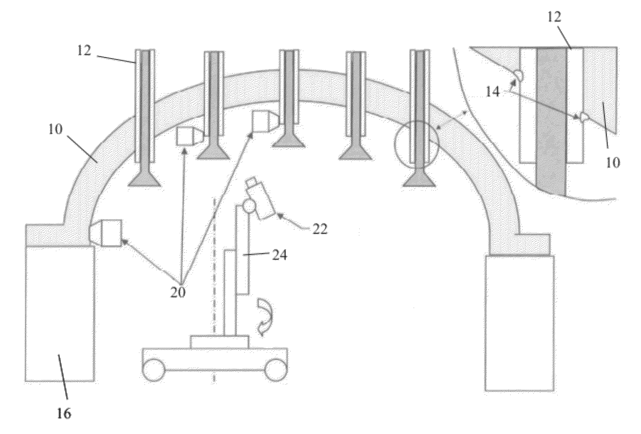
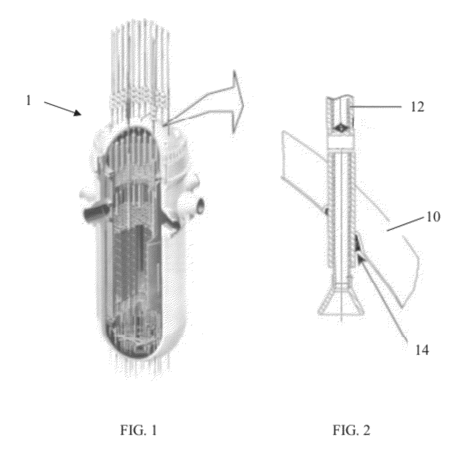
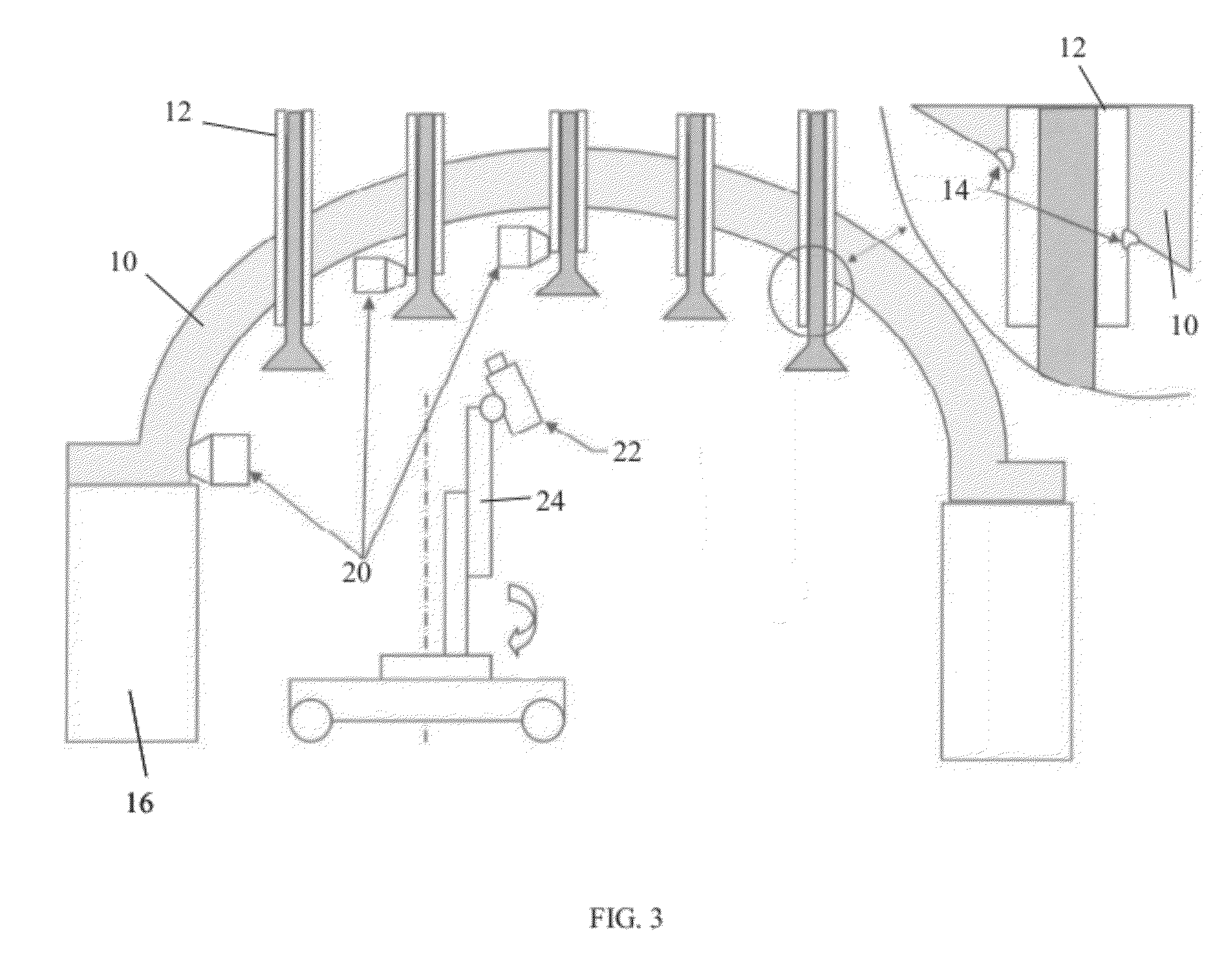
[0024]Vibrothermography, also known as sonic IR and thermosonics, is a nondestructive evaluation technique that uses sonic excitation (vibration) to preferentially heat cracks in metal, ceramics, polymers, and composites. This local temperature change may be detected remotely using an infrared (IR) camera. This phenomenon and general test approach is applied to the reactor vessel head by injecting a transient sonic excitation while monitoring the J-groove weld area with a remote infrared camera. Any cracks that “light-up” can be detected and marked for further characterization and evaluation or repair.

[0025]The instant system and inspection method provides advantages over other known vibrothermography or alternative non-destructive examination inspection systems and methods. The inventive technique can be implemented with simple remote tools that do not require complex motions to track the complex weld surface. The crack indication is visually clear and can readily be correlated wit...


PUM


Abstract

The present invention is related to a system and method of inspecting a weld. The weld to be inspected is subjected to a transient sonic excitation while the weld area is monitored using a remote infrared camera. The sonic excitation induces mechanical vibration, which causes heat generation at any cracks or other anomalies in the weld. The infrared camera detects any temperature differentials in the weld, indicating the presence of an anomaly. The system and method is particularly useful for welds in environments that are unsafe for extended human presence or that are crowded or otherwise inaccessible, such as with piping or other structural components.

Description

CROSS-REFERENCE TO RELATED APPLICATIONS[0001]This patent application claims the benefit of U.S. Provisional Patent Application No. 61 / 484,319 filed on May 10, 2011, which is incorporated herein by reference in its entirety.BACKGROUND OF THE INVENTION[0002]1. Field of the Invention[0003]The present invention relates to the inspection of welds using vibrothermography, and, more particularly, the present invention relates to inspecting and determining the quality of J-groove welds of a nuclear reactor pressure vessel (RPV) head and the RPV bottom mounted nozzles (BMNs) using vibrothermography.[0004]2. Description of the Related Art[0005]Nuclear reactors have a reactor cover or closure head through which a series of openings having tubes extending therethrough to the inside surface of the reactor are welded to the closure head by J-groove welds. These tubes have control rod drives and instrumentation packages sealably extending into the reactor internals. Similarly, the bottom portion o...

Claims


Application Information

Patent Timeline
IPC IPC(8): G21C17/00
CPCG01N25/72G21C17/017G21C17/01Y02E30/30G01N33/207
Inventor RENSHAW, JEREMY B.GLASS, III, SAMUEL W.THIGPEN, BRADLEY A.TAGLIONE, MATTHIEU
Owner AREVA NP SAS
Why Eureka
Try Eureka