Radiation imaging system

a radiation imaging and imaging system technology, applied in the field of radiation imaging systems, can solve the problems of poor image contrast, inability to obtain sufficient contrast for x-ray absorption contrast images, and inability to obtain adequate contrast for x-ray absorption contrast images, and achieve good phase contrast images

Inactive Publication Date: 2012-11-15
FUJIFILM CORP
View PDF5 Cites 41 Cited by
  • Summary
  • Abstract
  • Description
  • Claims
  • Application Information

AI Technical Summary

Benefits of technology

[0044]According to the present invention, a mathematical expression DX≠n×(p1′×p2′)/|p1′−p2′| is satisfied where p1′ denotes a period of the first periodic pattern image, relative to the second direction, at a position of the second grating, p2′ denotes a substantial grating pitch of the second grating r

Problems solved by technology

This causes a problem that in vivo soft tissue and soft material have small X-ray absorption properties, so sufficient contrast for the X-ray absorption contrast image cannot be obtained.
For example, articular cartilage and its surrounding synovial fluid, both constituting a human joint, are mainly made of water, so there is little difference between their amoun

Method used


Image

  • Radiation imaging system
  • Radiation imaging system
  • Radiation imaging system

Examples


first embodiment

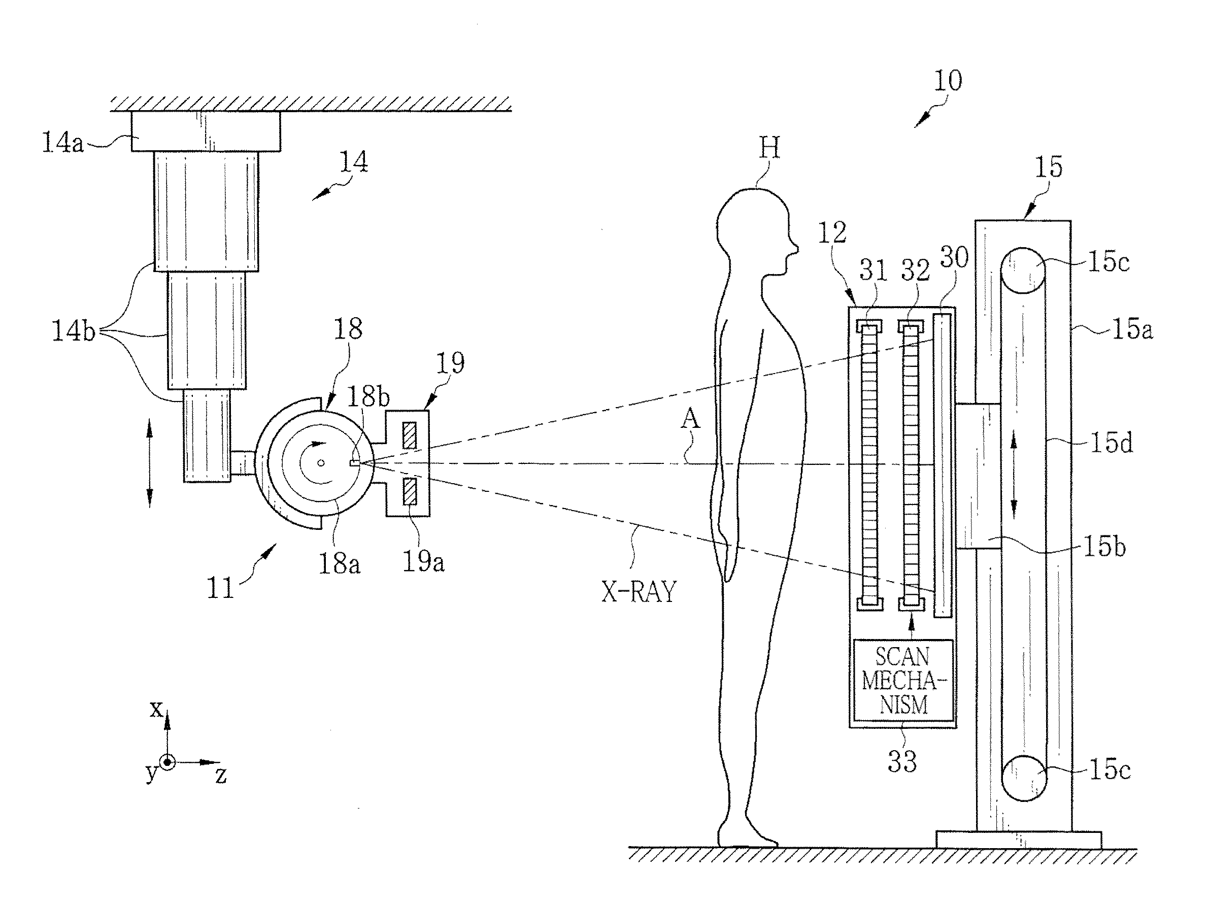
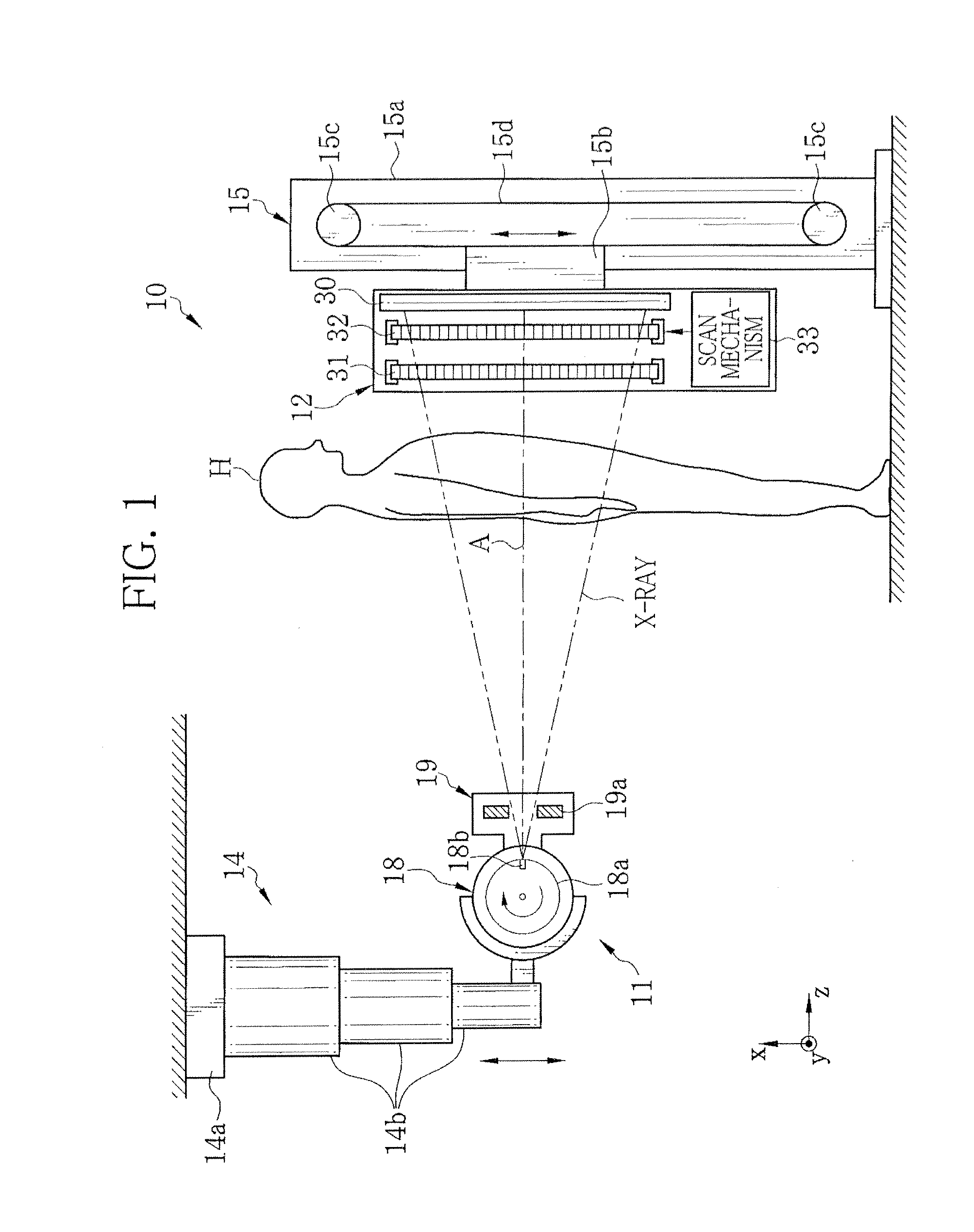
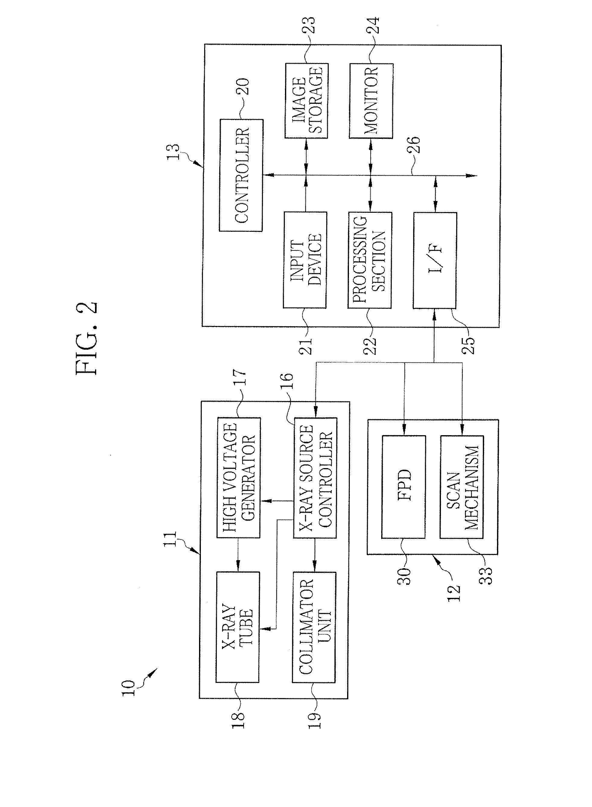
[0077]In FIGS. 1 and 2, an X-ray imaging system 10 according to a first embodiment of the present invention is an X-ray diagnostic apparatus for capturing an image of an object (patient) H in a standing position. The X-ray imaging system 10 is composed of an X-ray source 11, an imaging unit 12, and a console 13. The X-ray source 11 irradiates the object H with X-ray. The imaging unit 12 is opposed to the X-ray source 11, and detects the X-ray passed through the object H to generate image data. The console 13 controls the exposure of the X-ray source 11 and the image capture of the imaging unit 12 based on operation of an operator. The console 13 also processes image data, obtained by the imaging unit 12, to generate a phase contrast image.

[0078]An X-ray source holder 14 holds the X-ray source 11 such that the X-ray source 11 is movable in a vertical or up-and-down direction (x direction). The X-ray source holder 14 is suspended from a ceiling. An upright stand 15, placed on a floor,...

second embodiment

[0137]FIG. 15 shows an X-ray imaging system 60 according to a second embodiment of the present invention. The X-ray imaging system 60 is an X-ray diagnostic apparatus for capturing an image of an object (patient) H in a lying position. The X-ray imaging system 60 is provided with the X-ray source 11, the imaging unit 12, and a bed or table 61 on which the object H lies down. The X-ray source 11 and the imaging unit 12 are similar to or the same as those in the first embodiment. The components thereof are designated by the same numerals as in the first embodiment. Hereafter, differences between the first and second embodiments are described. Other configuration and operation are the same as those in the first embodiment, so the descriptions thereof are omitted.

[0138]In this embodiment, the imaging unit 12 is mounted below a table top 62 to oppose the X-ray source 11 via the object H. The X-ray source 11 is held by the X-ray source holder 14. An angle change mechanism (not shown) of t...

third embodiment

[0142]FIGS. 16 and 17 show an X-ray imaging system 70 according to a third embodiment of the present invention. The X-ray imaging system 70 is an X-ray diagnostic apparatus capable of capturing images of the object (patient) H in standing and lying positions. A rotary arm 71 holds the X-ray source 11 and the imaging unit 12. The rotary arm 71 is coupled to an upright support 72 in a rotatable manner. The X-ray source 11 and the imaging unit 12 are similar to or the same as those in the first embodiment. The components thereof are designated by the same numerals as in the first embodiment. Hereafter, differences between the first and third embodiments are described. Other configuration and operation are same as those in the first embodiment, so descriptions thereof are omitted.

[0143]The rotary arm 71 is composed of a U-shaped section 71a shaped approximately like a letter U and a linear section 71b connected to one of the ends of the U-shaped section 71a. To the other end of the U-sh...


PUM


Abstract

An X-ray imaging system is provided with an X-ray source (11), first and second absorption gratings (31, 32), and a flat panel detector (FPD) (30), and obtains a phase contrast image of an object H by performing imaging while moving the second absorption grating (32) in x direction relative to the first absorption grating (31). The following mathematical expression is satisfied where p1′ denotes a period of a first pattern image at a position of the second absorption grating (32), and p2′ denotes a substantial grating pitch of the second absorption grating (32), and DX denotes a dimension, in the x-direction, of an X-ray imaging area of each pixel of the FPD (30). Here, “n” denotes a positive integer.
DX≠n×(p1′×p2′)/|p1′−p2′|

Description

TECHNICAL FIELD[0001]The present invention relates to a radiation imaging system for capturing an image of an object using radiation such as X-ray, and more particularly to a radiation imaging system for performing phase imaging of an object.BACKGROUND ART[0002]Because X-ray attenuates depending on an atomic number of an element constituting a substance and density and thickness of the substance, it is used as a probe for inspecting the inside of an object. X-ray imaging is widely used in medical diagnoses and non-destructive inspections.[0003]In a general X-ray imaging system, an object is arranged between an X-ray source, for emitting X-ray, and an X-ray image detector, for detecting the X-ray, to capture an X-ray transmission image of the object. Each X-ray emitted from the X-ray source to the X-ray image detector is attenuated (absorbed) by an amount depending on the difference in object's properties (atomic number, density, thickness) existing on an X-ray path to the X-ray imag...

Claims


Application Information

Patent Timeline
IPC IPC(8): G01N23/04A61B6/00
CPCA61B6/022A61B6/03A61B6/06A61B6/4233A61B6/4441A61B6/4464G21K2201/06A61B6/502A61B6/5241G21K2207/005A61B6/4291G21K1/067G21K1/06A61B6/484
Inventor MURAKOSHI, DAITADA, TAKUJIAGANO, TOSHITAKATAKAHASHI, KENJI
Owner FUJIFILM CORP
Why Eureka
Try Eureka