Gas supply apparatus, thermal treatment apparatus, gas supply method, and thermal treatment method

Inactive Publication Date: 2012-11-15
TOKYO ELECTRON LTD
View PDF5 Cites 164 Cited by
  • Summary
  • Abstract
  • Description
  • Claims
  • Application Information

AI Technical Summary

Benefits of technology

[0013]To solve the above problems, the present invention provides a gas supply apparatus, a thermal treatment apparatus, a gas supply method, and a thermal treatment method that are used t

Problems solved by technology

In particular, when an atomic layer deposition (ALD) process in which a raw material gas is intermittently repeatedly supplied and stops from being supplied is performed to fo

Method used


Image

  • Gas supply apparatus, thermal treatment apparatus, gas supply method, and thermal treatment method
  • Gas supply apparatus, thermal treatment apparatus, gas supply method, and thermal treatment method
  • Gas supply apparatus, thermal treatment apparatus, gas supply method, and thermal treatment method

Examples


first embodiment

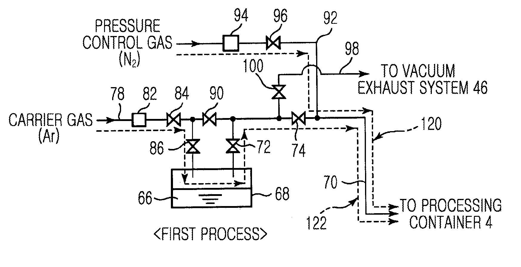
[0051]First, a thermal treatment method including an embodiment of a gas supply method according to the present invention will be described below. FIG. 3 is a flowchart for describing a thermal treatment method including the embodiment of the gas supply method according to the present invention FIGS. 4A and 4B are schematic diagrams for describing flow of gas using the embodiment of the gas supply method according to the present invention. In FIGS. 4A and 4B, the flow of gas is indicated by a dotted line arrow. A case where ZrCp(NMe2)3 is used as a raw material and a zirconium oxide thin film is formed by using O3, that is an oxidized gas, as a reaction gas will be described as an example.

[0052]In detail, the thin film may be formed by repeatedly performing a plurality of times one cycle including a process of alternately supplying the raw material gas and the reaction gas (O3) in a pulse shape in a predetermined supplying time and a process of stopping the supply of the raw materia...

second embodiment

[0067]Next, a thermal treatment method including another embodiment of a gas supply method according to the present invention will be described. First, in the previous embodiment described with reference to FIGS. 3 and 4, the differential pressure inside the raw material gas passage 70 is suppressed by simultaneously supplying the pressure control gas and the raw material gas accompanied with the carrier gas toward the processing container 4 in process S1. However, the present invention is not limited thereto, and a large amount of the carrier gas is previously supplied into the raw material gas passage 70 before supplying the raw material gas so that the differential pressure generated when starting the supply of the raw material gas may further be suppressed.

[0068]FIG. 5 is a flowchart for describing a thermal treatment method including another embodiment of a gas supply method according to the present invention. FIGS. 6A through 6C are schematic diagrams for describing flow of ga...

third embodiment

[0078]Next, a thermal treatment method including another embodiment of a gas supply method according to the present invention will be described. First, in the preceding process of the previous embodiment described with reference to FIGS. 5 through 6C, although the pressure control gas and the carrier gas are supplied, the supply of the carrier gas may be stopped and only the pressure control gas may be supplied so that a differential pressure generated when starting the supply of the raw material gas may be further suppressed.

[0079]FIG. 7 is a schematic diagram for describing flow of gas of a preceding process using another embodiment of a gas supply method according to the present invention. In FIG. 7, the flow of gas is indicated by a dotted line arrow. Also, like reference numerals in the following description denote like elements in FIGS. 3 to 6C, and thus, they will not be explained again. In the current embodiment, as shown in FIG. 7, before performing process S1, that is, imm...


PUM

PropertyMeasurementUnit
Pressureaaaaaaaaaa
Flow rateaaaaaaaaaa

Abstract

A gas supply apparatus including a raw material gas supply system supplying a raw material gas inside a raw material storage tank into the processing container by the carrier gas, the gas supply apparatus includes: a carrier gas passage introducing the carrier gas into the raw material storage tank, a raw material gas passage connecting the raw material storage tank and the processing container to supply the carrier gas and the raw material gas; a pressure control gas passage being connected to the raw material gas passage to supply the pressure control gas; and a valve control unit controlling an opening/closing valve to perform for starting a supply of the pressure control gas into the processing container and simultaneously starting supply of the raw material gas into the processing container from the raw material storage tank, and stopping the supply of the pressure control gas.

Description

[0001]CROSS-REFERENCE TO RELATED PATENT APPLICATIONS This application claims the benefit of Japanese Patent Application No. 2011-105145, filed on May 10, 2011 in the Japan Patent Office, the disclosure of which is incorporated herein in its entirety by reference.BACKGROUND OF THE INVENTION[0002]1. Field of the Invention[0003]The present invention relates to a thermal treatment apparatus for performing thermal treatment on an object to be processed such as a semiconductor wafer, and a gas supply apparatus, a thermal treatment method, and a gas supply method that are used together with the thermal treatment apparatus.[0004]2. Description of the Related Art[0005]In general, in order to manufacture a semiconductor integrated circuit, various processes, for example, a film-forming process, an etching process, an oxidization process, a diffusing process, a modification process, or a natural oxidization film removing process, are performed on a semiconductor wafer constituted of a silicon ...

Claims


Application Information

Patent Timeline
IPC IPC(8): F16K17/00C23C16/02
CPCC23C16/4482C23C16/455H01L21/0228H01L21/02189C23C16/45557Y10T137/0324Y10T137/0396Y10T137/7722H01L21/02H01L21/205H01L21/67017H01L21/67115
Inventor FURUYA, HARUHIKOSHIMA, HIROMITACHINO, YUSUKE
Owner TOKYO ELECTRON LTD
Why Eureka
Try Eureka