Mitral heart valve holder and storage system

a technology of mitral valve and storage system, which is applied in the field of medical devices, can solve the problems of complex delivery, deficiency of the prosthetic mitral valve, and significant morbidity and mortality of heart valve diseas

Active Publication Date: 2012-11-15
EDWARDS LIFESCIENCES CORP
View PDF49 Cites 19 Cited by
  • Summary
  • Abstract
  • Description
  • Claims
  • Application Information

AI Technical Summary

Benefits of technology

[0009]The present application discloses storage assemblies and systems for a flexible leaflet prosthetic heart valve that helps prevent suture looping. Each assembly includes a heart valve having an inflow end and an outflow end and a flow axis therebetween. The valve includes a plurality of generally axially-extending flexible commissure posts that end in tips circumferentially-spaced around the outflow end that support occluding flexible leaflets of the valve.

Problems solved by technology

Heart valve disease is a significant cause of morbidity and mortality, resulting from a number of ailments including rheumatic fever and birth defects.
When delivering a tissue type prosthetic valve in the mitral position, the outflow commissure posts are on the leading or blind side of the valve and may become entangled with pre-installed anchoring sutures.
The difficulty of delivery is compounded if the surgery is through a minimally-invasive access channel, a technique that is becoming more common.
The problem of entanglement is termed “suture looping,” and means that the suture that is used to attach or mount the valve to the heart tissue is inadvertently wrapped around the inside of one or more of the leading commissure post tips.
If this occurs, the looped suture may damage one of the tissue leaflets when tightly tied down, or may interfere with the valve implant procedure and prevent maximum coaptation of the valve leaflets, resulting in a deficiency in the prosthetic mitral valve, requiring an immediate explant.

Method used


Image

  • Mitral heart valve holder and storage system
  • Mitral heart valve holder and storage system
  • Mitral heart valve holder and storage system

Examples


Embodiment Construction

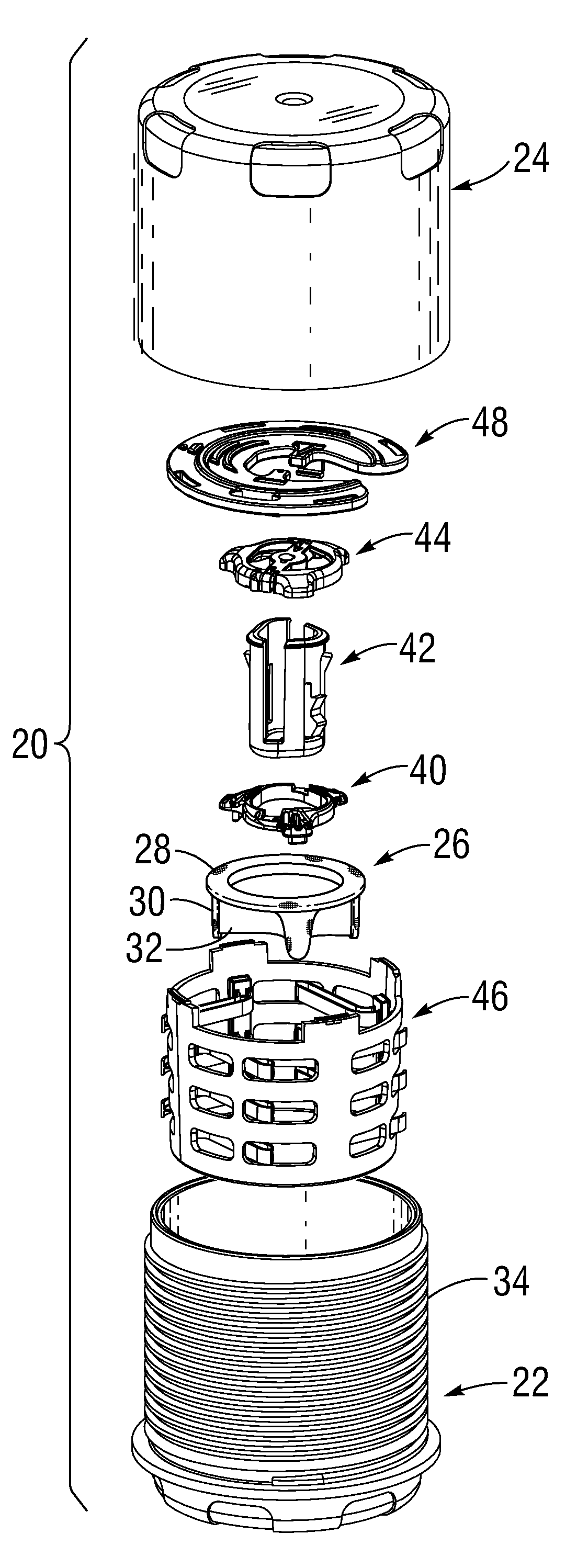
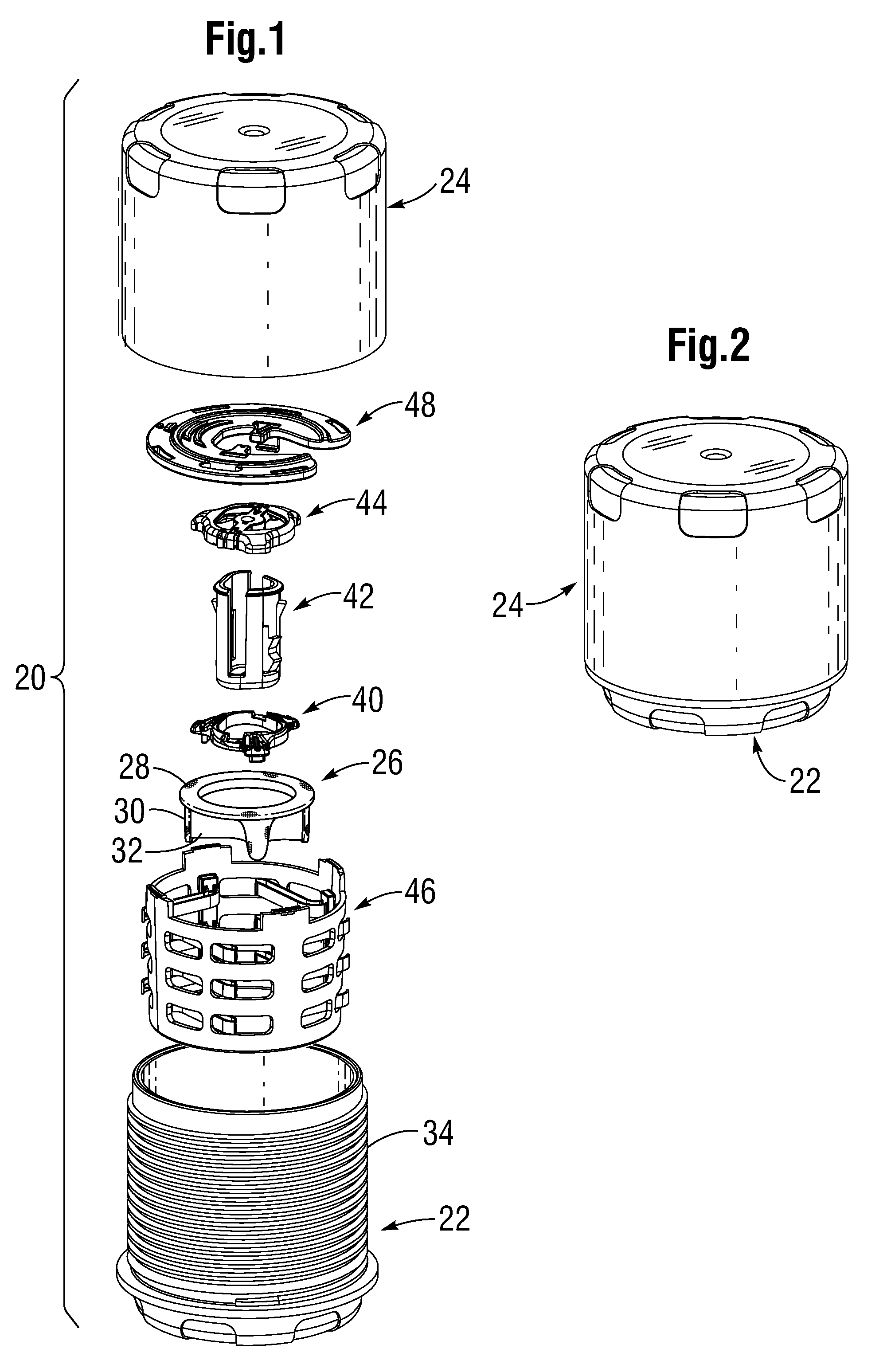
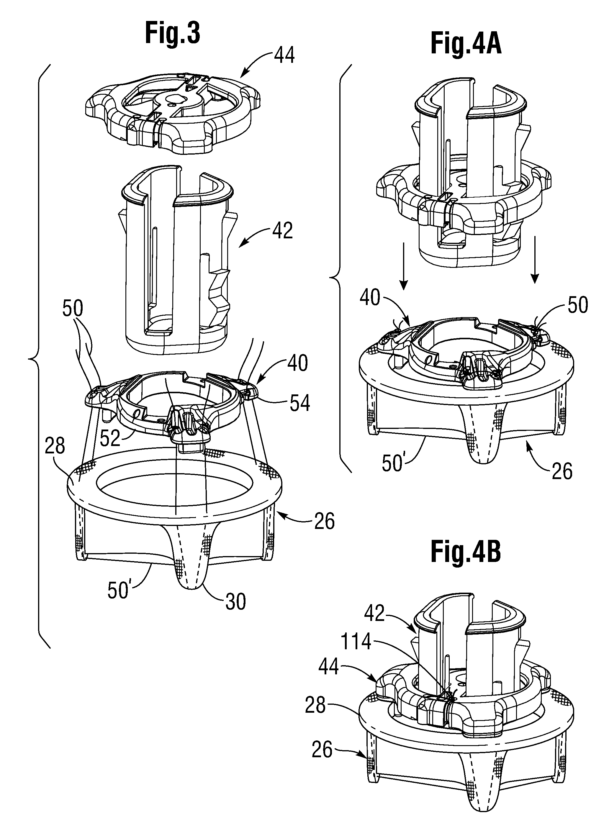
[0049]The present invention provides an improved heart valve holder for tissue-type prosthetic heart valves that facilitates implantation and reduces the chance of suture entanglement. The holder of the present invention is particularly useful for prosthetic mitral heart valves having commissure posts on the outflow side supporting flexible leaflets therebetween. The mitral position is such that the outflow end with commissure posts is the leading end as it advances toward the left ventricle during implantation, and thus the holder is attached to the inflow (i.e., trailing) end of the valve. Delivery of the valve to the mitral position involves sliding (parachuting) the valve down a plurality or array of sutures that have been pre-installed around the annulus and then passed through the valve sewing ring. The holder of the present invention constricts the valve commissure posts radially inward and at the same time moves attaching sutures axially to form a steep angle, or tent, thus ...


PUM


Abstract

An improved holder and storage system for a tissue-type prosthetic mitral heart valve that constricts the commissure posts of the valve and prevents suture looping. A rod axially movable relative to the holder tensions lengths of attachment sutures that extend between the commissure post tips to create a tent and flex the tips inward, thus helping to prevent looping of any of an array of pre-implanted sutures around the leading tips during delivery of the valve. The holder has a safety mechanism that prevents valve delivery before the rod is deployed. One embodiment automatically deploys the rod upon opening a storage jar. One embodiment permits a delivery handle to directly deploy the rod, while another uses a separate worm screw and coupling. A holder clip that attaches to a packaging sleeve may be formed of flexible members meshed together from which the heart valve and holder are easily pulled free to eliminate a step of decoupling the clip from the sleeve.

Description

FIELD OF THE INVENTION[0001]The present invention relates generally to medical devices, and more particularly to a holder that facilitates the implantation of a bioprosthetic mitral heart valve, and also to packaging for mitral valves that facilitates commissure constriction.BACKGROUND OF THE INVENTION[0002]Heart valve disease is a significant cause of morbidity and mortality, resulting from a number of ailments including rheumatic fever and birth defects. The natural heart valves are identified as the aortic, mitral (or bicuspid), tricuspid and pulmonary valves, and each has leaflets to control the directional flow of blood through the heart. Worldwide, approximately 300,000 heart valve replacement surgeries are performed annually, and about one-half of these patients receive bioprosthetic heart valve replacements, which utilize biologically derived tissues for flexible fluid-occluding leaflets.[0003]The most successful bioprosthetic materials for flexible leaflets are whole porcin...

Claims


Application Information

Patent Timeline
Patent Type & Authority Applications(United States)
IPC IPC(8): A61F2/24A61B19/00
CPCA61F2/0095A61F2250/001A61F2/2412A61F2230/0006A61F2220/0075A61F2/2409A61F2/2427
Inventor MURAD, MICHAEL C.KARAPETIAN, EMILADZICH, W. VASO
Owner EDWARDS LIFESCIENCES CORP
Why Eureka
Try Eureka