Gas sensor

a technology of gas sensor and sensor, which is applied in the direction of electrochemical generator, specific gravity measurement, instruments, etc., can solve the problems of difficult to change the temperature and resistor value of the first detection element, become difficult to change the temperature and resistor value, etc., to reduce thermal interference, reduce thermal interference, and improve accuracy

Active Publication Date: 2012-11-22
HONDA MOTOR CO LTD
View PDF8 Cites 7 Cited by
  • Summary
  • Abstract
  • Description
  • Claims
  • Application Information

AI Technical Summary

Benefits of technology

[0012]According to the above structure, the gas sensor has a simple structure which is provided with one element housing. Therefore, the gas sensor can be minimized easily. Also, the gas sensor is provided with one element housing, and the element housing is provided with one detection chamber. Therefore, if the gas sensor is provided with a heater for heating the detection chamber and a temperature sensor for detecting a temperature in the detection chamber, only one heater and only one temperature sensor are provided. For this reason, the number of parts is not increased significantly, and the cost for manufacturing the gas sensor is reduced.
[0026]According to the above structure, the cylindrical insulating members can reduce the thermal interference between the first detection element and the second detection element respectively.

Problems solved by technology

That is, it becomes difficult to change the temperature and the resistor value of the first detection element by the heat from the second detection element, and it becomes difficult to change the temperature and the resistor value of the second detection element by the heat from the first detection element.

Method used


Image

  • Gas sensor
  • Gas sensor
  • Gas sensor

Examples


first embodiment

[0042]Hereinafter, with reference to FIGS. 1-8, a first embodiment of the present invention will be explained.

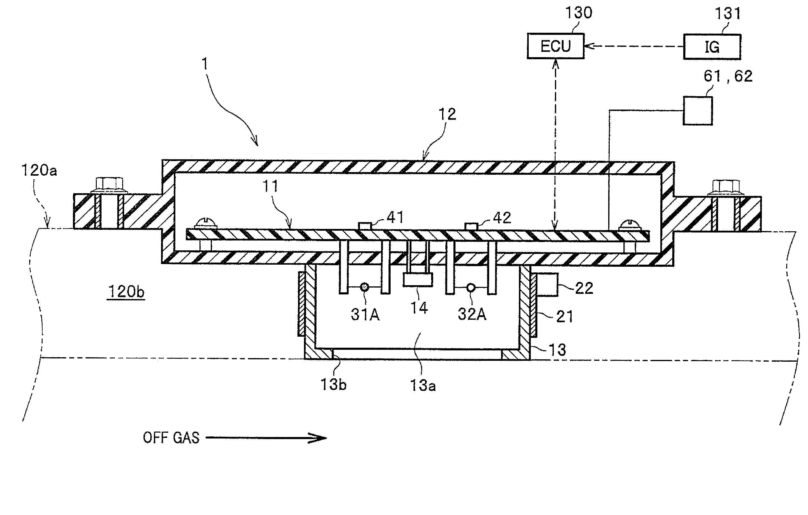
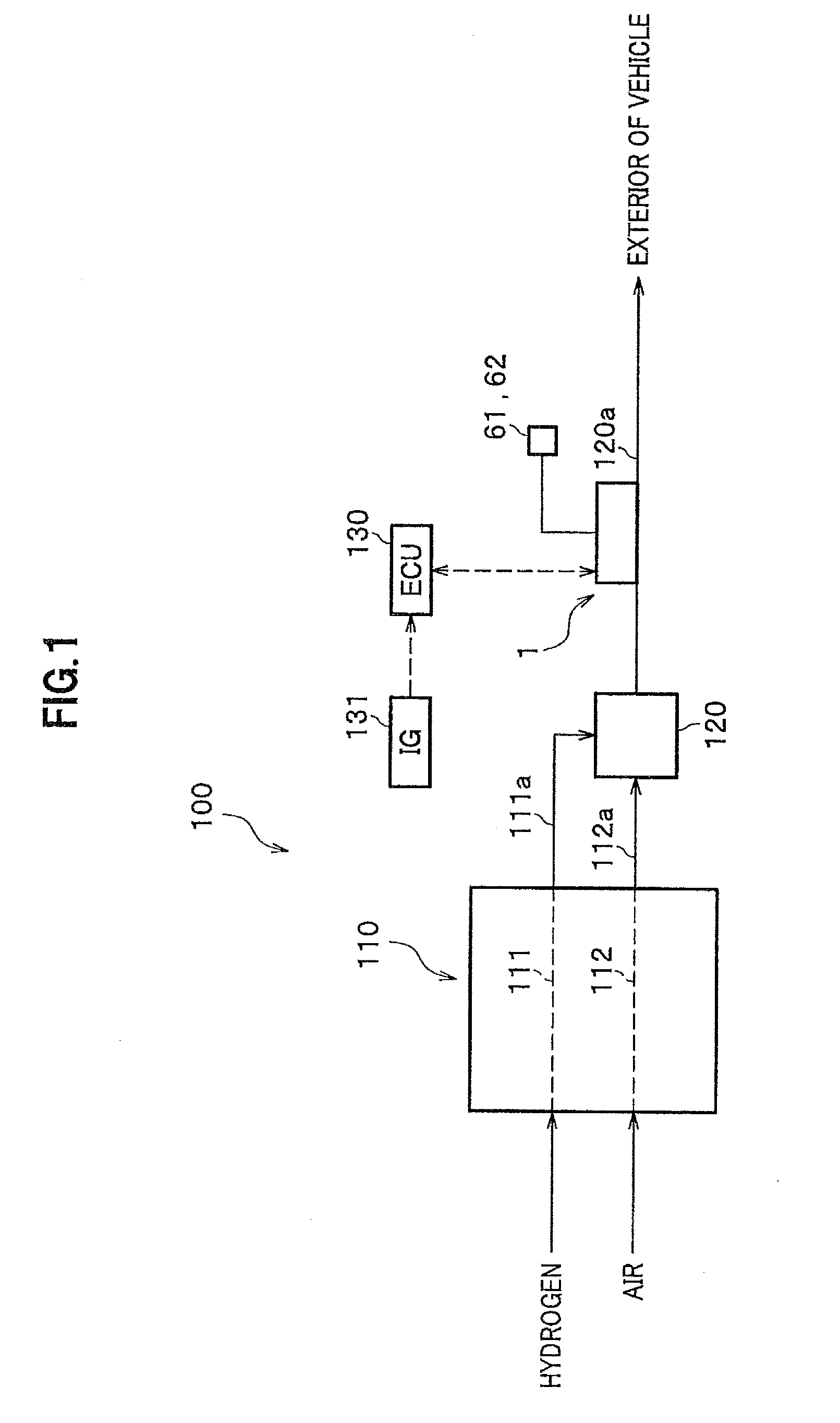
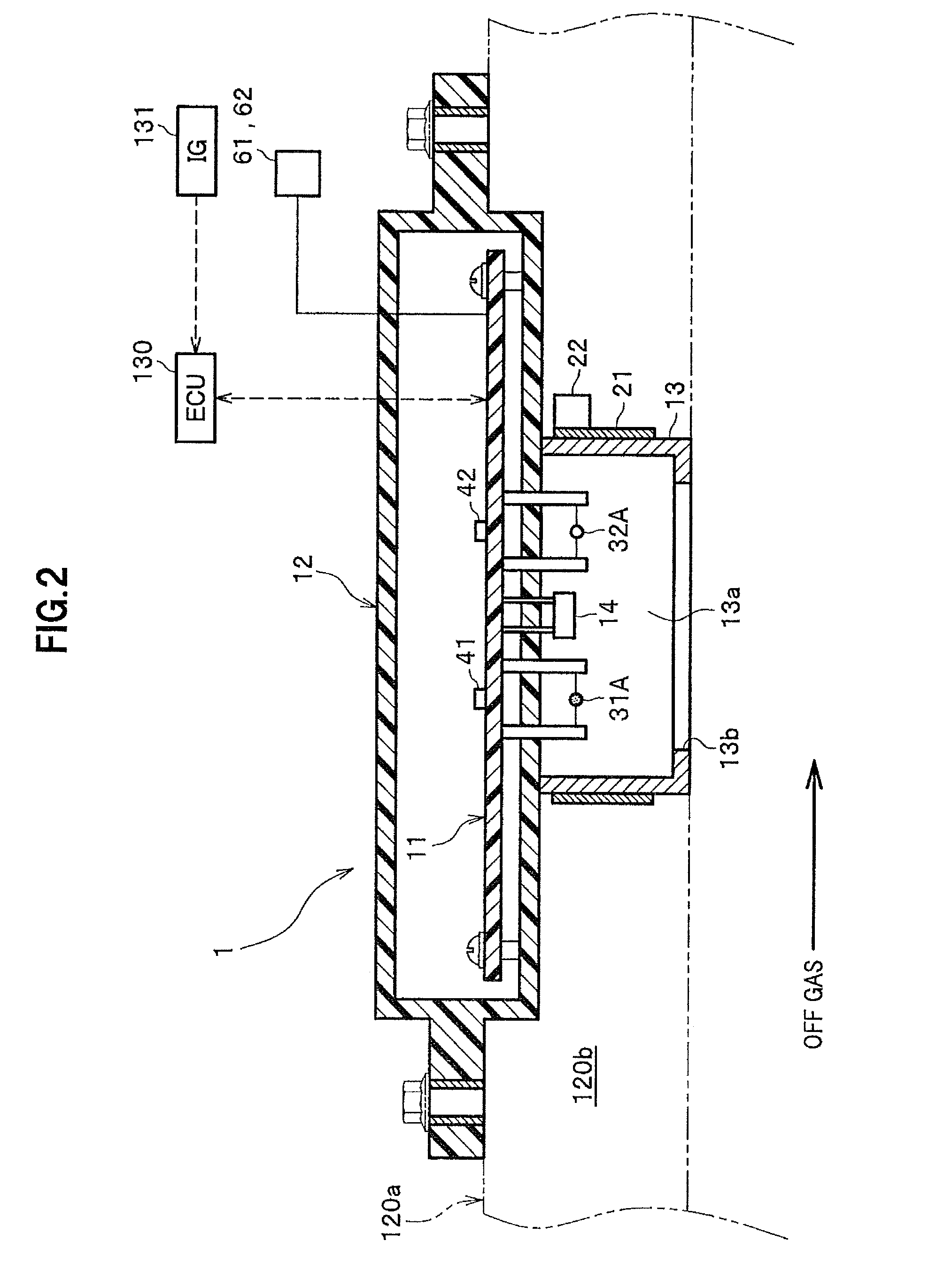
[0043]First, a fuel cell system 100 into which a hydrogen sensor 1 (a gas sensor) is integrated will be explained. The fuel cell system 100 is mounted on a fuel cell vehicle (a mobile unit), and is provided with a fuel cell stack 110 (a fuel cell), a dilutor 120, a hydrogen sensor 1, and an ECU 130 (Electronic Control Unit).

[0044]The fuel cell stack 110 is a Polymer Electrolyte Fuel Cell (PEFC), and is composed by stacking a plurality of single cells, each of which is made by sandwiching a Membrane Electrode Assembly (MEA) with separators (not shown). The MEA is provided with an electrolyte membrane (a solid polymer membrane), and an anode and a cathode for sandwiching the electrolyte membrane. A channel and a through hole which serve as an anode flow path 111 and a cathode flow path 112 are formed on each separator.

[0045]Also, when the hydrogen is supplied from a hydrogen t...

second embodiment

[0131]Next, with reference to FIG. 9, a second embodiment of the present invention will be explained. In addition, only different points from the first embodiment will be explained.

[0132]A hydrogen sensor 2 according to a second embodiment is provided with a normal detection element pair P3 which differs from the normal detection element pair P1. Also, for example, at the time of normal operation, the normal detection element pair P1 and the normal detection element pair P3 are alternately activated every predetermined time so as to increase lives of the normal detection element pair P1 and the normal detection element pair P3.

[0133]The normal detection element pair P3 is composed of a pair of a third detection element 31C and a third compensation element 32C. In addition, the hydrogen sensor 1 is provided with a third bridge circuit (not shown) like the first bridge circuit B1, and the third bridge circuit (not shown) is composed of the normal detection element pair P3.

[0134]A thir...

third embodiment

[0140]Next, with reference to FIGS. 10-11, a third embodiment of the present invention will be explained. In addition, only different points from the first embodiment will be explained.

[0141]A hydrogen sensor 3 according to the third embodiment is provided with a cross-shaped insulating member 15 which is made of a resin (e.g., polyphenylene sulfide. etc.). However, the insulating member 15 may be a corrosion-resistant metal (e.g., SUS, etc.).

[0142]The insulating member 15 is provided with a first wall 15a and a second wall 15b crossing at a mid points thereof in the horizontal plane. The first wall 15a extends between the normal detection element pair P1 and the reference detection element pair P2 in a direction parallel to the first arrangement direction D1 and the second arrangement direction D2. The second wall 15b extends between the first detection element 31A and the first compensation element 32A of the normal detection element pair P1, and between the second detection eleme...


PUM

PropertyMeasurementUnit
angleaaaaaaaaaa
temperatureaaaaaaaaaa
concentrationaaaaaaaaaa

Abstract

A simple gas sensor for detecting a concentration of a detected gas with high accuracy, in which a thermal interference can hardly occur between a normal detection element pair and a reference detection element pair, is provided.

Description

CROSS REFERENCE TO RELATED APPLICATION[0001]This application claims the priority of Japanese Application No. 2011-114213, filed on May 20, 2011, the entire specification, claims and drawings of which are incorporated herewith by reference.BACKGROUND OF THE INVENTION[0002]1. Field of the Invention[0003]The present invention relates to a gas sensor.[0004]2. Description of the Related Art[0005]In recent years, a fuel cell which attracts attention as a power source of a fuel cell vehicle, etc., exhausts hydrogen (a detected gas) unconsumed in power generation from an anode. This hydrogen is diluted with a cathode off gas (a dilution gas) from a cathode of the fuel cell, and is exhausted to an exterior (an outside) of the vehicle.[0006]A hydrogen concentration of the gas (a diluted gas) exhausted to the external of the vehicle in the above described manner is detected by a catalytic combustion type hydrogen sensor (a gas sensor) (see JP 2004-251862 A). Also, since a detection element to ...

Claims


Application Information

Patent Timeline
Patent Type & Authority Applications(United States)
IPC IPC(8): G01N27/04
CPCG01N27/16G01N33/005Y02E60/50H01M8/04097H01M8/04402H01M8/0662
Inventor TSUKABAYASHI, SHUNJIOISHI, HIDETOSHIOKAJIMA, KAZUHIRO
Owner HONDA MOTOR CO LTD
Why Eureka
Try Eureka