Circuit and method for performing arithmetic operations on current signals

a current signal and circuit technology, applied in the field of circuits and methods for performing arithmetic operations on current signals, can solve the problems of communication or even a complete host-slave interaction, rfid systems can be very sensitive to rf distortion, and the dynamic range of a-d conversion is limited

Active Publication Date: 2012-11-22
IDT EURO GMBH
View PDF4 Cites 7 Cited by
  • Summary
  • Abstract
  • Description
  • Claims
  • Application Information

AI Technical Summary

Benefits of technology

[0018]It is an objective of the present invention to provide a circuit and related method for performing arithmetic operations on current signals that operates safely.

Problems solved by technology

Signals that go beyond this saturation limit will be clipped and thus distorted which prevents full-scale signal processing and therefore must be circumvented.
Additionally, RFID systems can be very sensitive to RF distortions, which might prevent communication or even a complete host-slave interaction.
Because the A-D conversion is limited in dynamic range and is therefore also limited in the digital measurement results, the effective dynamic range and digital resolution, respectively, for the difference itself is less than for the individual signal current.
Therefore, the problem arises of how to obtain an amplified, digitized difference between two separate current signals; whereas the full ADC resolution can be utilized to digitize the difference itself.
Moreover, the RF-transmission and especially the double A-D conversion typically consume more power than a single A-D conversion and respective measurement results transmission.
An additional problem lies in the limited absolute signal range and TIA gain in combination with the required gain to realize potential full-scale amplification.
If the TIA gain is limited and a higher gain for the signal difference is required, single “saw-tooth-like” integration would not yield sufficient amplification.
Hence, the potential difference output would not be correct.

Method used


Image

  • Circuit and method for performing arithmetic operations on current signals
  • Circuit and method for performing arithmetic operations on current signals
  • Circuit and method for performing arithmetic operations on current signals

Examples


Embodiment Construction

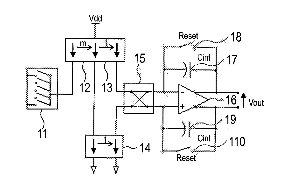
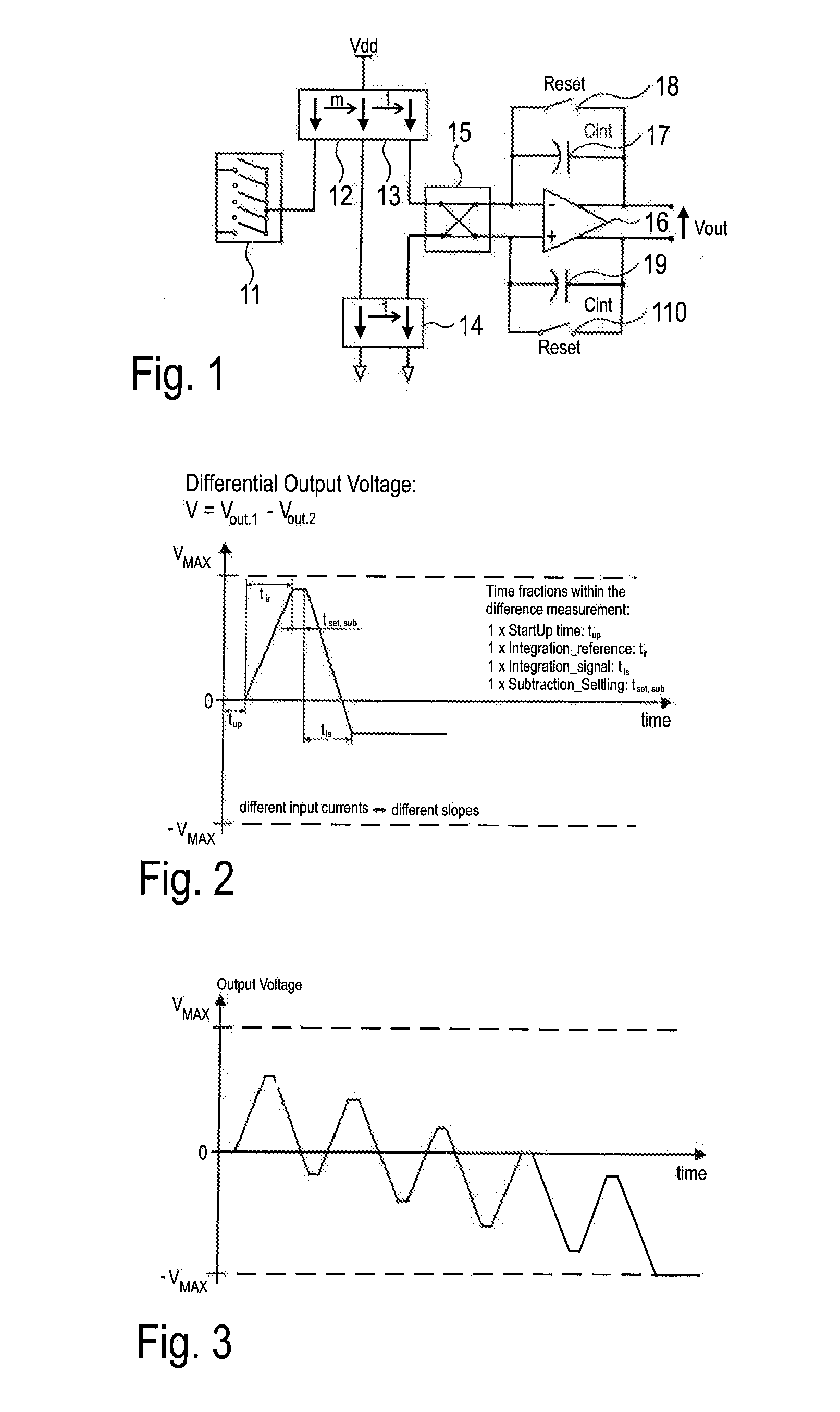
[0054]FIG. 1 shows one embodiment of the circuit. The circuit comprises an input means 11 being configured to selectively receive a current from a plurality of currents; a first current mirror 12 with mirror ratio m; a second current mirror 13; a third current mirror 14; a cross-multiplexer 15; and a differential capacitive transimpedance amplifier 16. A first capacitance 17 and a first switching element 18 are connected in parallel to the negative input port and a first output port of the differential capacitive transimpedance amplifier 16. A second capacitance 19 and a second switching element 110 are connected in parallel to the positive input port and a second output port of the differential capacitive transimpedance amplifier 16. The input means 11 are connected to the input port of the first current mirror 12. The output port of the first current mirror 12 is connected the input ports of the second 13 and third 14 current mirror. The output port of the second current mirror 13...


PUM


Abstract

A circuit for performing arithmetic operations includes a differential capacitive transimpedance amplifier (CTIA) and a cross-multiplexer. The cross multiplexer forwards the current to be integrated out of a plurality of current sources either to the positive input port of the differential CTIA for positive integration in direct mode or to the negative input port of the differential CTIA for negative integration in reverse mode.

Description

CROSS REFERENCE TO RELATED APPLICATIONS[0001]This application claims priority to European application No. 11164023.1 filed on Apr. 28, 2011, the entire contents of which is hereby incorporated herein by reference.TECHNICAL FIELD[0002]The present invention relates to a circuit and method for performing arithmetic operations on current signals. The present invention specifically relates to a circuit and method for difference measurement and transimpedance amplification of separate current signals.BACKGROUND ART[0003]In discrete and integrated analog / mixed-signal circuits, signal sources can provide currents for which the difference carries certain sensor information. Specifically, in optical sensor systems where a light intensity difference must be measured, separate photo diodes with different spectral sensitivity or geometrical orientation provide light-intensity-proportional currents and can therefore be interpreted as a current source in this sense. The information of interest lie...

Claims


Application Information

Patent Timeline
Patent Type & Authority Applications(United States)
IPC IPC(8): H03L5/00
CPCG06G7/14
Inventor MAILAND, MARKOGETZLAFF, STEFAN
Owner IDT EURO GMBH
Why Eureka
Try Eureka